This thread has been locked.

If you have a related question, please click the "Ask a related question" button in the top right corner. The newly created question will be automatically linked to this question.

SN74AUP1T08: Help with output oscillating on Schmitt Trigger AND

Part Number: SN74AUP1T08
Other Parts Discussed in Thread: SN74AUP1G97

Hello,

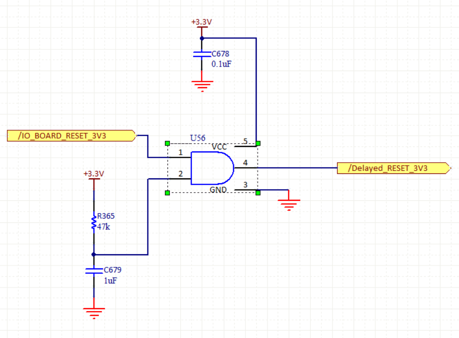
I have a Schmitt Trigger AND gate I am using for timing at reset. The inputs to the AND gate are one digital, and one RC timing circuit. I am not measuring much noise on the RC input and the line does not appear noisy until the oscillations happen. The oscillations eventually stop after a few microseconds and the output goes high.

Things I have tried so far:

1. Putting a 0.1nF, 1nF, or 10nF capacitor in parallel with the 1uF timing capacitor. There is no difference in output with any of these parallel capacitors.

2. Lifting the output pin and measuring the signal when it is not connected to the board to eliminate any possible reflections/impedance mismatches. The oscillations are then removed, but a single low pulse follows the low to high transition.

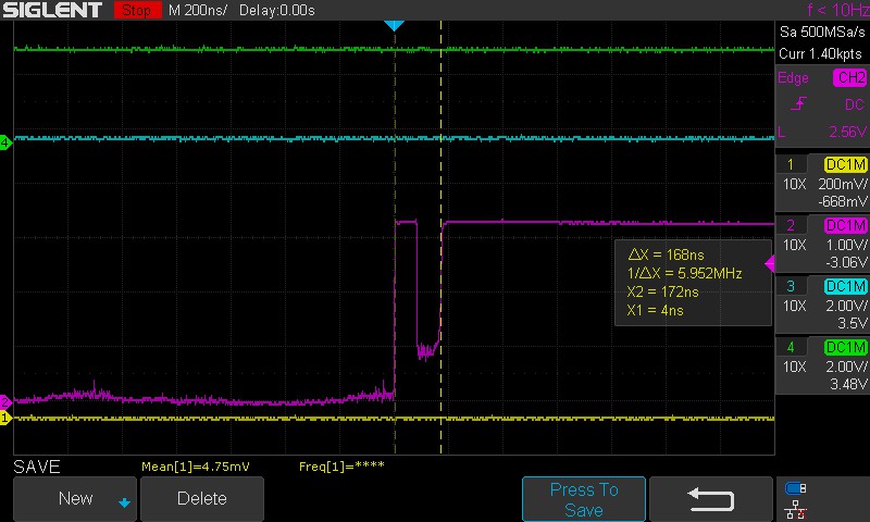
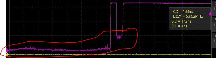
The frequency of the oscillations are about 25MHz. The width of the first high pulse is 150-170ns. Please see attached schematic and oscilloscope captures.

Thanks,

Matt

Schematic:

Original scope capture of the problem. The purple is the output pin, the blue is the other AND input (digital), yellow is the RC timing input pin.

Scope capture of the output pin lifted. Purple is the output pin, green is the other AND input.

Scope capture with the output pin lifted and a 0.1nF capacitor in parallel with the 1uF timing capacitor.

  • That ringing in the second scope capture is probably a measurement artifact. How did you connect the ground clip? What is the board layout?

    I guess the noise comes through the supply (3.3 V or GND) and is caused by the increasing power consumption of the other circuit starting up.

    You could try the SN74AUP1G97, which has more hysteresis. But it would be a better idea to prevent the noise from reaching the AND gate; try a capacitor in parallel with R365, or improving the decoupling of U56.

  • Hello,

    Thank you for your response. I tried a parallel capacitor with the resistor which did not solve the problem. I have verified the decoupling (no observable dips across the supply pins), and added a 1uF and 10uF in parallel just for good measure. These also did not solve the problem.

    I have switched to only measuring the 2 signals of interest with shorter spring ground leads which removed the grounding problem. The resulting output is a much cleaner signal from the RC circuit on the AND gate input.

    Please let me know what else I should try.

    Thanks,

    Matt

  • The low level of the output looks funny, especially during the low pulse. Is this with the output open, or is there any load?

    Please show the board layout.

  • Hi Matt,

    It looks like the output is having trouble holding the line low in a couple of your scope shots:

    This might be caused by something connected to the output, but it also could be coming from a damaged output driver. ESD strikes are the most common cause for something like that to happen.

    Have you tried swapping to a new device to see if the issue clears?  Are there ESD safeguards in place for your rework station?

  • The output from those captures are with the output pin lifted, so there is no load connected to the driver.

    I have tried on 5 different devices shipped from Digikey in an ESD safe bag, all with the same result. The rework station has an ESD mat and ESD strap, and the product has a metal enclosure I have been using to carry from the rework station to the bench.

    I can try reworking again taking special care to ESD precautions. Is the part particularly sensitive to ESD?

  • The latest scope capture is with the output open, no load. 

    Here is the layout.

  • Hey Matt,

    No, standard ESD precautions should be sufficient. It sounds like you're doing everything right.

    The AUP family of logic uses a rather unique structure to achieve maximum low power operation. I have run into a similar situation once before recently (E2E thread: https://e2e.ti.com/support/logic/f/151/t/954173 )

    Since these two devices use the same internal design, I suspect that a very slow input signal can cause this type of oscillation. I'm currently working to determine if this is verifiable with my design & simulation team.

     In the other case, the input signal came from a very weak driver (> 200kohm series input resistance).  Is this true in your circuit as well?

  •  Yes the driver to that input is weak, it is an RC timing circuit with a 47k ohm resistor and 1uF capacitor. 

  • Oh right - sorry I was thinking it was the /IO_BOARD_RESET_3V3 input for some reason, which is obviously incorrect.

    Can you check with different timing components? If you have a similarly sized 10uF + 4.7kohm would be a good test. Or perhaps just reduce the time constant a bit -- not sure if that delay is a hard requirement.

    It's possible that it's just a limitation of the design for the input ramp rate. It will take a while for me to verify (possibly weeks).

    I would recommend swapping to an LVC family device, but we don't have an exact replacement. The LVC1G57 could be used, but it's a different pinout, so a board spin would be required.

  • Hello,

    I tried a 10uF and a 1k ohm RC timing circuit and the low pulse is still present in the output.

    Using separate Schmitt Trigger and AND gate devices solved the problem.

    I will try the LVC1G57 when I get a chance and report back.

    Thanks,

    Matt