

Hi All,
I would like to ask some questions on logic devices.
I.
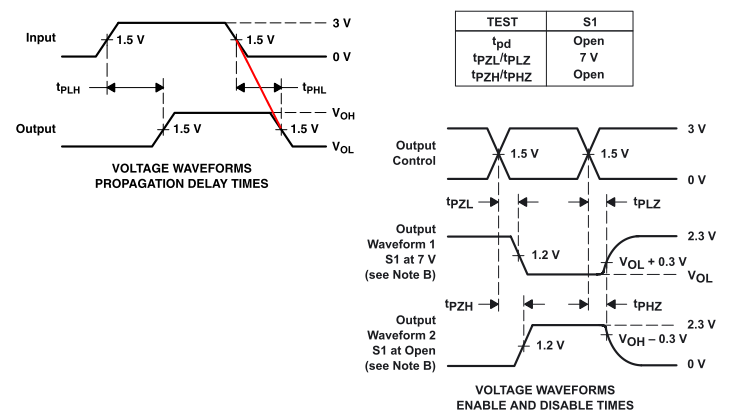
The first question is that does the output voltage level equal input level? Fig. 1 is from the PARAMETER MEASUREMENT INFORMATION part of
1. SN74CBT3257 Mux / Demux
2. SN74CBT16292 Mux / Demux
and these contents are the same in the documents of these two devices.
From the left of Fig. 1, if seems that input’s 1.5V, which is half in the rise between low and high, is the same in output. So does this suggest that these logic devices keep the output voltage level the same as input voltage level?
II.
The second question is on the right of Fig. 1, in which I don’t understand what the curved shape mean. In the dashed box on the left, the transition is straight; why on the right it is a smooth curve?
II.
The third question is on these logic devices’ effect on impedance matching. In this attached Fig. 2, data lines coming out from DM6437 (these pins are multiplexed with COUTxx pins so the net is labeled as COUTxx) are first connected to Mux/Demux before connecting with memory devices (NOR flash and SRAM). There are termination resistors of 22 Ohm at the DSP pins to matching with the impedance of tracks.
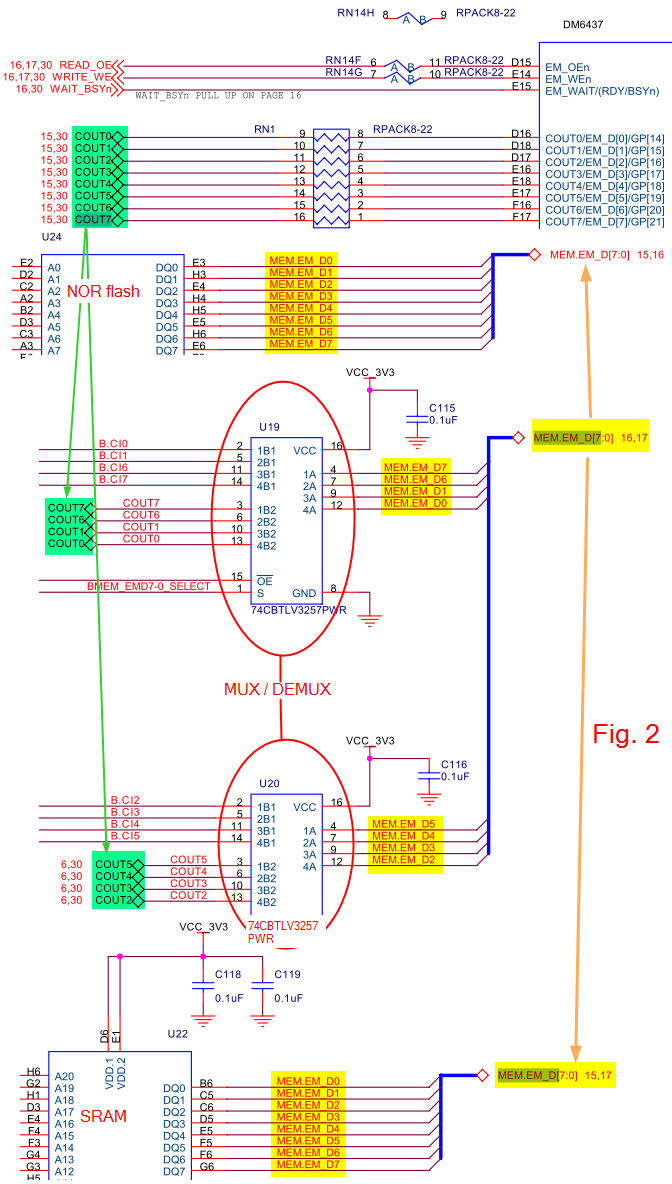
But does the impedance matching take the intermediate Mux/Demux into account? The formula for impedance-matching resistor value is:
Rdriver + Rresistor = Zo
So what is the role of these Mux/Demux here? The schematics is from EVM6437 by Spectrum Digital so I believe the matching is good, but if I am removing these intermediate mux/demux, do I need to change the value of those impedance-matching resistors?
Thanks,
Zheng
