Other Parts Discussed in Thread: SN74LS374
I'm pulling my hair out and banging my head against the wall. I've been trying to solve a very strange problem with the SN74LS245NSR chip for the past two weeks to no avail. Here's the scoop:
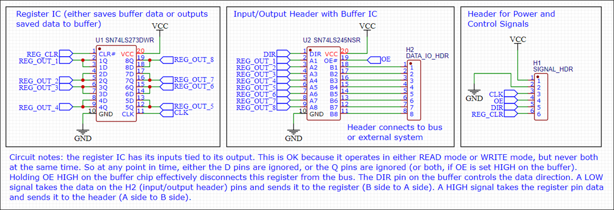
I'm trying to build a very simple tri-state register circuit by combining the SN74LS273DWR and SN74LS245NSR chips on a small PCB that has eight header pins for 8 bits of input or output, and a 6 pin header that connect power, ground, clock, OE, DIR (buffer direction), and CLR ( register clear). Literally that's all that's on the board - two chips and two headers - no resistors, no capacitors, etc. The register chip (well, actually it's an octal flip-flop I'm using as a register) either saves a values from the input/output header, or sends its value out to the input/output header. The buffer chip sits in between the register chip and the input/output header in order to control whether its in INPUT mode or OUTPUT mode. This circuit is meant to connect to a bus for either reading values and saving them, or outputting previously saved values to the bus.
I have a prototype of this exact circuit on a breadboard, except using the PDIP version of those chips (SN74LS273N and SN74LS245N) and that circuit works 100% OK.
BUT, the PCB version of the circuit with the SMD version of the chips just doesn't work. And it's the SN74LS245NSR chip specifically that is giving me problems on the PCB. Here's what happens:
1) I hookup the 8 bit input/output header to a bus, and input any binary number across those pins.
2) I send a clock pulse to the 'LS273 register chip.
3) It latches the values just fine, BUT...
4) I try and set a different binary number across the input pins.
5) Send clock pulse.
6) Set the DIR pin high (in order to change the buffer direction, now my input pins should be the output of the register) and check the output pins' logic level (they should match the values I just saved).
7) The first six bits save fine, but sometimes bit 7 or bit 8, sometimes both, are NOT saved! Typically they're LOW when I tried to save HIGH.
8) I can repeat this process over and over, but still, bits 7 or 8, but sometimes both, are never saved into the register.
9) If I disconnect power from the circuit, wait a few seconds, and power back up, the circuit will once again always save correctly just the FIRST time, but not bits 7 and 8 on any subsequent attempt.
I have narrowed down the problem to some strange behavior of the buffer chip (SN74LS245NSR). When I'm inputting values into the register (DIR pin set LOW), so B pins go to A pins, the FIRST time, everything is OK. My MM shows correct voltage levels on all B input pins and all A output pins. But the _second_ time and on, the buffer chip totally misbehaves and does NOT send the correct voltage from B pins 7 and 8 to A pins 7 and 8. The voltage on the B side is about 3.4V, but the output A pins (7 or 8, sometimes both) show a voltage of only 1.05V, which is not even in logic range for this chip. So therefore, when I pulse the clock on the register in order to save the binary number on the input header, it doesn't get the correct voltage to represent either a HIGH or LOW from the buffer chip for bits 7 & 8.
I had the PCB boards manufactured by JLCPCB and have used them many times, never had an issue with their boards. This time however, I bought the 'LS245 chips from them (also TI brand) and had the factory solder on the chips for me. So when I got the boards in the mail, I only had to solder on the register chip myself. I would figure since the buffer chip was soldered by a professional machine that there's a very low chance they would burn out those chips.
At first, I thought maybe the factory used fake TI chips and that was the problem. I got 5 boards from them, and ALL 5 had the same issue. So I ordered a new set of boards _without_ the buffer chips pre-soldered and ordered a set of SN74LS245NSR chips directly from TI. Obviously TI chips directly from TI are going to be real, so when I got the new set of boards, I quickly went to solder on both chips and thought everything was going to OK. But no! Same issue!!
OK, at this point, I think, let's make sure it's not the connected 'LS273 chip that's causing some voltage variation... So I take a brand new board and solder _only_ the 'LS245 (buffer) chip to it and proceed to test the circuit just like before but without the register chip. Obviously the buffer chip doesn't have a clock pin, so that part is irrelevant. Here's what I see:
1) Buffer chip _sometimes_ outputs the correct values on bits 7 & 8, but also other pins are sometimes affected.
2) The buffer chip is warm when it's DIR pin is high (no matter whether a register chip is on the PCB or not).
3) When I change the DIR pin to LOW, the wattage usage of the entire circuit jumps a full whole watt and the chip gets extremely hot (eventually way too hot to touch).
I know what you're thinking - I damaged the chip while soldering, and that's exactly what I thought at first. Then I tried soldering on 5 more chips, to 5 different boards, and still the same behavior. By the second board, I lowered my soldering iron temperature to 270 C and started using thinner solder. At 270C it takes a bit longer for solder to start to melt on the pins. Previously my temp was 350 C, which might be too high for SMD's. But I thought 270 C was OK? Is it not?
There was one attempt where I was _very_ careful with soldering and never left the iron on any pin for more than 2 seconds (also at 270 C). But still got the same bad behavior from the chip.
Then I started a process of elimination - I soldered _only_ these pins: VCC, ground, DIR, OE. I just wanted to see if my wattage/current monitor (which is a USB monitor since my circuit takes power from a USB port) would show unusually high wattage. It did _not_. Then I soldered on just data pin B 8. And, sure enough, got extremely high wattage readings again and the chip got extremely hot with OE set to LOW. When I move OE to HIGH, the wattage goes down by a whole watt, and the chips cools, but still hot enough to feel significantly warm (more than I think it should be for only having 5 pins hooked up).
Anyway, I've tried to solder on the buffer chip as delicately as I can at least 8 or 9 times already (using brand new chips each time, directly from TI). But still it's acting like I'm damaging them in the soldering process.
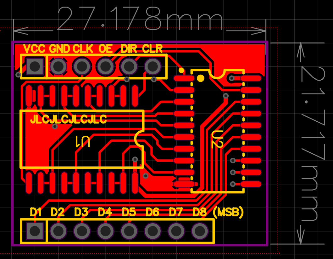
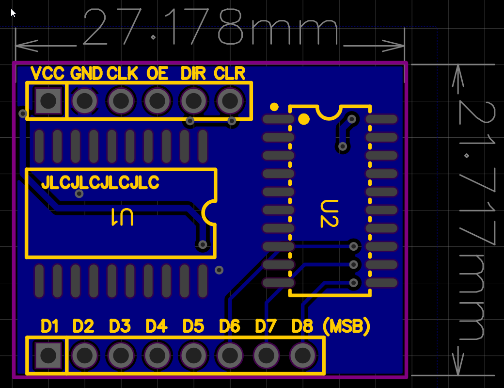
I simply don't know whether there's a problem with the PCB's (it's really small, like about 30 x 30mm), the way I'm soldering on the chips, or the circuit itself. The datasheet says to watch the input current for the buffer chip, but my breadboard version of this circuit works just fine even if I connect the data pins directly to VCC or ground. But who knows, maybe the input current is too high for the SMD version of the chips, I don't know.
I have no idea what to think right now, or where to go from here. What do you guys think??
Let me know if you want me to attach a screenshot of the schematic or PCB design.
Thanks!
-Greg


