This thread has been locked.

If you have a related question, please click the "Ask a related question" button in the top right corner. The newly created question will be automatically linked to this question.

TXS0108E: TXS0108E fails for an I2C communication

Part Number: TXS0108E
Other Parts Discussed in Thread: TXS0102, TXS010

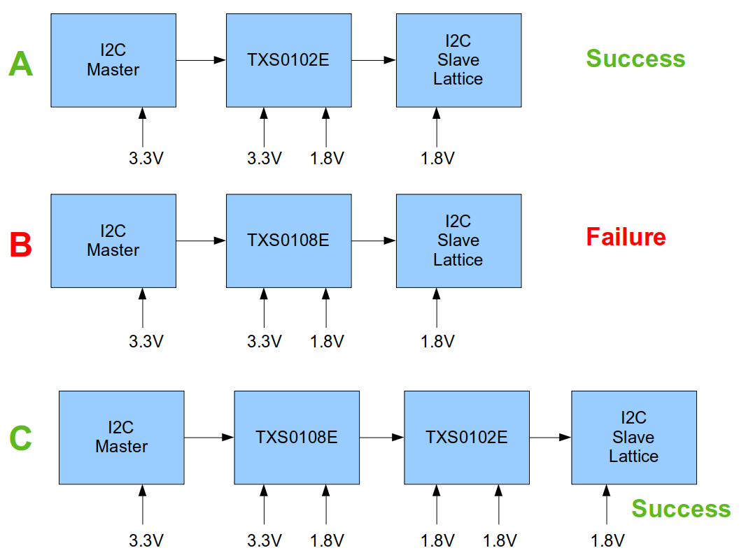
I have a failed I2C communication using TXS0108E while TXS0102 is working. Here are some tests:


A. SUCCESS using TXS0102
B. FAILURE using TXS0108E
C SUCCESS using TXS0108E and then TXS0102

More precisely, I have:

- A standard I2C communication at 100kHz from an ARM module powered at 3.3V
- A native hardware-based I2C slave in a Lattice chip powered at 1.8V
- Shift level using TXS010[2_8E] from VCCB=3.3V to VCCA=1.8V
- No pull-up or pull-down resistor on both sides
- Note that the scenario C is a success while being out of the specs for TXS0102 as VCCB is < 2.3V.
- The scenario B, which is a failure, shows a lost communication: usually a NACK detected by the master during a write operation.

I have another I2C slave chip in scenario B and it works as expected. So TXS0108E can translate the I2C communication but not for this Lattice chip which has a hardware-based I2C slave module. It's just this particular Lattice chip that doesn't like the I2C presented by TXS0108E.

In the datasheet, TXS0102 has 10k pull-up while TXS0108E has a funky 40k and 4k pull-up when level is high or low.

As I'm in production, could I fix the scenario B with some pull-ups or something?

  • Another difference is that the 0108E has an edge accelerator also for falling edges. It is unclear why the I²C slave would be affected by that.

    Can you show oscilloscope traces of the failing communication?

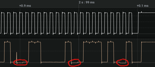
  • Scenario B failure with Lattice chip:

    Scenario B success with another chip (Omnivision):

    Scenario C success:

    All those traces are taken at the same location, just after the TXS0108E with the same software driving the I2C master. The Lattice chip has a built-in I2C slave. The comparison with the Omnivision shows that it doesn't drive down SDA "very quickly".

  • Hey Gregoire,

    It seems those spikes present with the Lattice Chip are the cause of the issue. Could you zoom in on one of those spikes for better detail? Those spikes not being present with the Omnivision at least allows us to focus on what could be causing this with the Lattice chip. Could I also get scope shots of scenerio A to see if those spikes are present?

  • I think that a more fair statement would be that the association of the Lattice chip and TXS0108E creates the issue.

    Here is the same failure with a close up:

    TXS0102 has always worked very well for me. There are some other E2E threads of problems with TXS0108E.

    And my 3 scenarios clearly show that TXS0108E is the culprit.

    Can you start suggesting some fixes to try? Can I help the chip with some pull-up / pull-down or something? I have the feeling that I need to do things on SDA - SCL seem pretty clean.

  • SDA is driven by both the master and the slave; the spike happens at the handover, and should, in theory, not be a problem.

    Can you show the waveforms at the master and at the slave?

  • Hey Gregoire,

    I would like to confirm that by seeing a scope shot of Scenerio A. Right now, I don't know how the TXS0102 reacts with the lattice chip and all I know is that there is a scope shot with those spikes that's 'failing' and then a scope shot with spikes that's 'successful'. This would typically lead me to believe that they aren't the main culprit. I can't suggest a fix to a problem that hasn't been identified. Adding pull-ups/pull-downs could possibly make the problem worse and its rare those fix issues with TXS devices since they aren't recommended to be used in conjunction with those devices. 

  • I don't think that the spikes are the problem because they occurred at the falling edge of the clock.

    Here is the trace at the master during the failure of scenario B:

    It's 3.3V as it's on the master side (left side) of TXS0108E in scenario B.

    I don't have immediate access to the hardware of scenario A. But I can tell you think that the spikes are there in scenario A.

    Here is the trace at the master side (left side) of TXS0108E in scenario C which includes TXS0102. Spikes are present:

  • Most of the waveforms do not show proper stop bits, but I guess they were not captured.

    When looking at the first waveform (B failure), one can see that the last ACK from the slave happens too early by one clock pulse (after only seven data bits):

    I would guess that the slave saw one rising edge too many. This is not visible in the waveform, but it might be possible that there is enough ringing for a false edge.

    Is there a long trace after the TXS0108E? (There seems to be enough for a little bit of crosstalk.) Try adding a series resistor, or an RC filter.

  • Thank you for the analysis.

    No, the traces after the last translator to Lattice is very short (around 5 millimeters).

    This is very disappointing because scenario C works. The problem only occurs when the Lattice chip is presented the TXS0108E traces.

    Series resistor: you mean 22 ohm? RC filter? Do you have any suggestion of values?

  • @DylanHubbard, here is the trace of scenario A (success) on the master side. There are spikes. So now that you have the requested traces, what do you suggest for a fix?

  • The TXS is designed to output sharp edges for up to 70 pF loads, but that does not matter for I²C.

    Try 100 pF, and adjust until the overshoots go away.

  • 1. I want to make sure that I understand correctly. You are suggesting that I should add a 100pF capacitor from SCL-1V8 to ground after TXS0108E. I have tried and it didn't seem to fix the problem. Am I correctly understanding what you are suggesting?

    2. I'm still confused what's going on. Here is a capture of the scenario B when it fails. I don't understand why it seems that the master gets stuck and it doesn't continue to output the clock.

  • 1. Yes, add the capacitor there, to slow down the edges. You might also need a small series resistor. If the waveform does not improve, enlarge the capacitor.

    2. The slave pulls the SDA line low (too early by two clock cycles). The master interprets this as lost arbitration.