

Other Parts Discussed in Thread: SN74AC14
Hello all,
I'm on my way to design a nanosecond pulse generator. I've reached the 10 ns time scale with 10 ns resolution. I believe that this is where transmission effects are to be considered.
I'd like to describe my configuration and raise some questions about it:
The output driver is a SN74LVC1G14 (Vcc = 5 V) with an added 25 Ohm series resistor as described in the FAQ .
This is a 100 ns pulse when connected to the 1 MOhm input of an oscilloscope. One can observe a fast edge with no ringing:
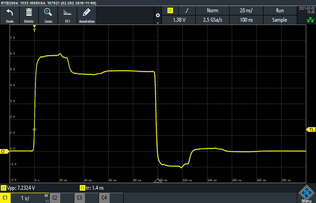
However, the graph shows an "overshoot" or "hump" that ranges from 0 to about 27 ns.
I believe this is due to reflections, i.e. reflections from the oscilloscope (open circuit, reflection with same amplitude) back to the driver and from the driver (short circuit, reflection with negative amplitude) to the oscilloscope. So after about 27 ns the reflected signal interferes with the original signal. As the reflected signal has a negative amplitude, it decreases the overall amplitude at the oscilloscope input. That would also explain the negative overshoot or "dip" from 100 ns to about 125 ns.
The cable length between driver and oscilloscope is 2.5 m of coaxial cable. A reflection back and forth will travel a distance of 5 m. I calculated that a signal will travel about 25 ns in a coaxial cable of 5 m. That fits well with the observation, I think. Further, changing the cable length changes the width of the "hump".
Does that make sense?
To eliminate reflections, I added a 50 Ohm load resistor at the oscilloscope input. Then the signal looks great:

The reflections are gone, however, the amplitude is only 3 V and not 5 V any more.
How do I achieve full 5 V at the scope input?
Further, a SN74LVC1G14 that drives 75 Ohm with Vcc = 5V probably exceeds its absolute maximum rating (least from a DC point of view).
Will this driver be fine or are other drivers recommended?
Thanks a lot.
Dan

