This thread has been locked.

If you have a related question, please click the "Ask a related question" button in the top right corner. The newly created question will be automatically linked to this question.

SN74LVC1G123: Which schematic would be better?

Part Number: SN74LVC1G123

Dear team, 

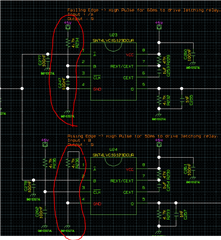
At datasheet, we can see that "Falling edge sensitive input; requires B and CLR to be held high." and "Rising edge sensitive input; requires A to be held low and CLR to be held high."

And then, Which schematic would be better with pull up/down resistor or without pull up/down resistor on A/B/CLR port?

1. without pull up/down

2. with pull up/down resistor 

Thank you. 

  • As far as the device itself is concerned, pull-up/-down resistors are not necessary.

    Please note that R234 and R236 are not pull-up resistors; the R/C combination generates a rising edge shortly after power up.

  • Hello Ladisch, 

    Thank you for your comment.

     The second schematic is from customer, R234 is pull up resister to hold high to meet datasheet comment("Falling edge sensitive input; requires B and CLR to be held high."). input signal is A. 

    For R236 also is designed as pull down resister to hold low. the capacitor is for CLR. 

    Will adding R234,236 cause side effect? Please review it again and let me know your opinion. 

    Thank you. 

  • Sorry; I was talking about R234 and R235 (the font is quite unreadable).

    On U23, the B and /CLR pins are connected together, so both will be low at startup, and rise later.

    R236 is not needed (but harmless). If B should always be high, then it needs a separate connection to VCC (with or without a pullup).