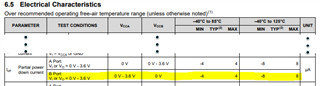
I was wondering what would happen with the subject device if VCCA is powered, EN is active (held low), translation DIR is from A-to-B, but VCCB is not powered.
Will there be any leakage current/voltage from VCCA rail to the VCCB rail?
I was wondering what would happen with the subject device if VCCA is powered, EN is active (held low), translation DIR is from A-to-B, but VCCB is not powered.
Will there be any leakage current/voltage from VCCA rail to the VCCB rail?