Other Parts Discussed in Thread: MSP-EXP432E401Y, SYSBIOS
SUMMARY OF THE ISSUE
I need to perform as many analog to digital conversions per second as possible. My understanding is that there are 2 ADC modules and each is capable of collecting 2 MSPS by setting the ADCCLK to 32 MHz. The default configuration appears to run the PLL at 240 MHz, SYSCLK at 120 MHz, and the ADCLK off the PIOSC at 16 MHz. With the PLL at 240 MHz, there is no ADC_CC<CLKDIV> setting to achieve 32 MHz in support of the 2 MSPS per module maximum collection rate (CLKDIV 8 achieves 30 MHz and CLKDIV 7 is about 34 MHz which exceeds the 32 MHz limit).
I want to set the PLL to 480 MHz, divide it down by 4 to get the 120 MHz SYSCLK and divide it down by 15 to get the 32 MHz ADCCLK. However, the Boot_sysCtlClockFreqSetI function in Boot_sysctl.c appears to have an error. The values are off by a factor of two. Investigation revealed that there was a Silicon Errata SYSCTL#22 for a similar product, TM4C129x (SPMZ850G-October 2013 - Revised March 2017). The errata documents a problem with the RSCLKCFG<PSYSDIV> hardware and fudging these values in the software was part of the workaround (Appendix 3). There is no such errata in the MSP43E errata document (SLAZ709-October 2017).
Finally, the Technical Reference says several times that PSYSDIV must always be set to 0x1 (resulting in a divide by two). I need to set it to 0x3 resulting in a divide by 4.
QUESTIONS
Does the MSP432Y have the same silicon defect in its RSCLKCFG<PSYSDIV> hardware?
Should the workaround for the TM4C129x defect be removed from the MSP432Y TIRTOS?
Can I use N=0x4, Q=0x0, and PSYSDIV=0x3 to get 480 MHz PLL and 120 MHz SYSCLK?
ADDITIONAL INFORMATION
I am developing on the MSP-EXP432E401Y Launch Pad prototyping board. My IDE is Code Composer Studio Version: 9.0.1.00004. I use TIRTOS 3_20_00_10.
I have a 25 MHz crystal connected to the OSC0 OSC1 pins.
Examining registers in a debugger run, I see:
PLLFREQ0<PWR>=0x1
PLLFREQ0<MFRAC>=0x0
PLLFREQ0<MINT>=0x60 (96 decimal)
PLLFREQ1<Q>=0x1
PLLFREQ1<N>=0x4
PLLSTAT<LOCK>=0x1
RSCLKCFG<USEPLL>=0X1
RSCLKCFG<PLLSRC>=0x3 (MOSC)
RSCLKCFG<PSYSDIV>=0x1
According to the equations in section 4.1.5.5.1, PLL Configuration, of the Technical Reference Manual, this results in a PLL VCO frequency of 240 MHz and SYSCLK frequency of 120 MHz. By default the ADCCLK appears to be running off the PIOSC at 16 MHz.
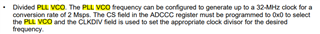
I then modified Boot_sysctl.c to jam set PLLFREQ1<Q>=0x0 and RSCLKCFG<PSYSDIV>=0x3 just before powering on the PLL hoping this will result in a PLL VCO frequency of 480 MHz and SYSCLK frequency of 120 MHz. I have also set ADC_CC<CS>=0x0 (PLL VCO) and ADC_CC<CLKDIV>=0xE (14 decimal) to hopefully achieve an ADCCLK frequency of 32 MHz.
I have three sysctl.c files in my installation. The driverlib and sysbios files use 240000000 for the 480 MHz frequency. I assume driverlib is for the application to use and modify - I do not use it. When I run, the system is using the sysbios file.
C:\ti\simplelink_msp432e4_sdk_3_20_00_10\source\ti\devices\msp432e4\driverlib\sysctl.c
C:\ti\simplelink_msp432e4_sdk_3_20_00_10\kernel\tirtos\packages\ti\sysbios\family\arm\msp432e4\init\Boot_sysctl.c
//*****************************************************************************
//
// Look up of the possible VCO frequencies.
//
//*****************************************************************************
static const uint32_t g_pui32VCOFrequencies[MAX_VCO_ENTRIES] =
{
    160000000,                              // VCO 320
    240000000,                              // VCO 480
};
The catalog file uses 480000000 for the 480 MHz frequency. I have no idea what a catalog is. I don't think this is being used by TIRTOS or my application.
C:\ti\simplelink_msp432e4_sdk_3_20_00_10\kernel\tirtos\packages\ti\catalog\arm\cortexm4\tiva\ce\Boot_sysctl.c
//*****************************************************************************
//
// Look up of the possible VCO frequencies.
//
//*****************************************************************************
static const uint32_t g_pui32VCOFrequencies[MAX_VCO_ENTRIES] =
{
    320000000,                              // VCO 320
    480000000,                              // VCO 480
};