


Hello Team,
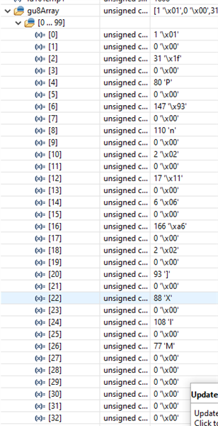
I'm working on uDMA receive from UART. I'm using TM4C1294XL to receive bytes from another MCU(MSP430) here, I'm unable to understand that the received bytes are in alternate in gu8Array(internal buffer) also sometimes in Zigzag(unable catch what's happening). Team, please let me know why is this happening. Am i missed anything in configuration of DMA receive? Please look into the images attached below. Any help would be very thankful.
int main()
{
Init Sysclk();
Init Gpio();
Init_UDMA();
  while(1)
  {
  while(MAP_UARTCharsAvail(UART0_BASE))
     {
         //
         // Get the interrupt status.
         //
         ui32Status1 = MAP_UARTIntStatus(UART0_BASE, true);

         //
         // Clear the asserted interrupts.
         //
         MAP_UARTIntClear(UART0_BASE, ui32Status1);

         //
         // Check the DMA control table to see if the ping-pong "A" transfer is
         // complete.  The "A" transfer uses receive buffer "A", and the primary
         // control structure.
         //
         ui32Mode = ROM_uDMAChannelModeGet(UDMA_CHANNEL_UART0RX | UDMA_PRI_SELECT);

         //
         // If the primary control structure indicates stop, that means the "A"
         // receive buffer is done.  The uDMA controller should still be receiving
         // data into the "B" buffer.
         //
         if(ui32Mode == UDMA_MODE_STOP)
         {
         ROM_uDMAChannelTransferSet(UDMA_CHANNEL_UART0RX | UDMA_PRI_SELECT,
                                   UDMA_MODE_BASIC, (void *)(UART0_BASE + (uint16_t)(UART_O_DR & 0xFFFF)),
                                   gu8Array, sizeof(gu8Array));
         }

         //
         // If the UART1 DMA TX channel is disabled, that means the TX DMA transfer
         // is done.
         //
         if(!ROM_uDMAChannelIsEnabled(UDMA_CHANNEL_UART0RX))
         {
             //
             // Start another DMA transfer to UART1 TX.
             //
             ROM_uDMAChannelTransferSet(UDMA_CHANNEL_UART0RX | UDMA_PRI_SELECT,
                                        UDMA_MODE_BASIC, (void *)(UART0_BASE + (uint16_t)(UART_O_DR & 0xFFFF)),
                                        gu8Array, sizeof(gu8Array));

             //
             // The uDMA TX channel must be re-enabled.
             //
             ROM_uDMAChannelEnable(UDMA_CHANNEL_UART0RX);
             ROM_uDMAChannelRequest(UDMA_CHANNEL_UART0RX);
         }
     }
  }
}

void Init_UDMA()
{
       //
       // Enable the uDMA controller at the system level.  Enable it to continue
       // to run while the processor is in sleep.
       //
       ROM_SysCtlPeripheralEnable(SYSCTL_PERIPH_UDMA);
       ROM_SysCtlPeripheralSleepEnable(SYSCTL_PERIPH_UDMA);

       //
       // Enable the uDMA controller error interrupt.  This interrupt will occur
       // if there is a bus error during a transfer.
       //
       ROM_IntEnable(INT_UDMAERR);

       //
       // Enable the uDMA controller.
       //
       ROM_uDMAEnable();

       //
       // Point at the control table to use for channel control structures.
       //
       ROM_uDMAControlBaseSet(pui8ControlTable);

    //
    // Enable the GPIO Peripheral used by the UART.
    //
    SysCtlPeripheralEnable(SYSCTL_PERIPH_GPIOA);

    //
    // Enable UART0.
    //
    SysCtlPeripheralEnable(SYSCTL_PERIPH_UART0);


    //
    // Enable processor interrupts.
    //
    IntMasterEnable();

    //
    // Configure GPIO Pins for UART mode.
    //
    GPIOPinConfigure(GPIO_PA0_U0RX);
    GPIOPinConfigure(GPIO_PA1_U0TX);
    GPIOPinTypeUART(GPIO_PORTA_BASE, GPIO_PIN_0 | GPIO_PIN_1);

    UARTConfigSetExpClk(UART0_BASE, g_ui32SysClock, 1000000,
                            (UART_CONFIG_WLEN_8 | UART_CONFIG_STOP_ONE |
                             UART_CONFIG_PAR_NONE));

    UARTFIFOEnable(UART0_BASE);

    UARTFIFOLevelSet(UART0_BASE, UART_FIFO_TX4_8, UART_FIFO_RX4_8);


       //
       // Enable the UART for operation, and enable the uDMA interface for both TX
       // and RX channels.
       //
      // MAP_UARTEnable(UART0_BASE);
       MAP_UARTDMAEnable(UART0_BASE, UART_DMA_RX | UART_DMA_TX);

       //
       // Put the attributes in a known state for the uDMA UART1RX channel.  These
       // should already be disabled by default.
       //
       MAP_uDMAChannelAttributeDisable(UDMA_CH8_UART0RX,
                                       UDMA_ATTR_ALTSELECT | UDMA_ATTR_USEBURST |
                                       UDMA_ATTR_HIGH_PRIORITY |
                                       UDMA_ATTR_REQMASK);

       //
       // Configure the control parameters for the primary control structure for
       // the UART RX channel.  The primary contol structure is used for the "A"
       // part of the ping-pong receive.  The transfer data size is 8 bits, the
       // source address does not increment since it will be reading from a
       // register.  The destination address increment is byte 8-bit bytes.  The
       // arbitration size is set to 4 to match the RX FIFO trigger threshold.
       // The uDMA controller will use a 4 byte burst transfer if possible.  This
       // will be somewhat more effecient that single byte transfers.
       //
       MAP_uDMAChannelControlSet(UDMA_CH8_UART0RX | UDMA_PRI_SELECT,
                                 UDMA_SIZE_16 | UDMA_SRC_INC_NONE | UDMA_DST_INC_16);

       //
       // Configure the control parameters for the alternate control structure for
       // the UART RX channel.  The alternate contol structure is used for the "B"
       // part of the ping-pong receive.  The configuration is identical to the
       // primary/A control structure.
       //
       MAP_uDMAChannelControlSet(UDMA_CH8_UART0RX | UDMA_ALT_SELECT,
                                 UDMA_SIZE_16 | UDMA_SRC_INC_NONE | UDMA_DST_INC_16);

       MAP_uDMAChannelEnable(UDMA_CH8_UART0RX);
       MAP_uDMAChannelEnable(UDMA_CH9_UART0TX);

       //
       // Enable the UART DMA TX/RX interrupts.
       //
       MAP_UARTIntEnable(UART0_BASE, UART_INT_DMARX | UART_INT_DMATX);


       MAP_UARTEnable(UART0_BASE);
    //
    // Enable the UART interrupt.
    //
       MAP_UARTIntEnable(UART0_BASE, UART_INT_RX | UART_INT_RT); //| UART_INT_9BIT);
}


