This thread has been locked.

If you have a related question, please click the "Ask a related question" button in the top right corner. The newly created question will be automatically linked to this question.

TMS570LS1224: TMS570LS1224 : Analog loopback

Part Number: TMS570LS1224
Other Parts Discussed in Thread: HALCOGEN

Hi,

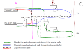
Can you please help me in explaining the analog loopback. 

Is it done by physically tying together the MOSI and SOMI pins and  calling the  

spiEnableLoopback(spi_selected_address, analog_loopback); and then monitoring the receive buffer ?

Do I have to do anything extra to this ?

Regards

Sherry

  • Hello Sherry,

    When using analog loop back it is not necessary to make a physical loop back circuit in your design/PCB. 

    Note in the diagram that the area shown as 'A' is the digital logic part of the module, the area indicated as 'B' is the analog buffers for taking the digital signals out to the real world (still inside the chip), and the area indicated as 'C' is outside the chip or at the pin level of the device. 

  • Thank you . That was very clear. In the Tech Ref manual it was not very clear. 

    One more query, if I call the function spiEnableLoopback(spiREG1, Analog_Lbk) from Halcogen,

    which is the type of analog loopback this is enabling, whether it enables the Analog loopback through receive buffer or analog loopback through transmit buffer or both?

  • This function supports both digital loopback and analog loopback. When Loopbacktype = Analog_Lbk, the analog loopback is enabled.

    RXPENA = 0 (bit 0 of IOLPBKTSTCR register), so the analog loopback is through the transmit pin.

  • Thank you for your reply.