This thread has been locked.

If you have a related question, please click the "Ask a related question" button in the top right corner. The newly created question will be automatically linked to this question.

EK-TM4C1294XL: UART3 Receive with uDMA Issue for Customised Boards

Part Number: EK-TM4C1294XL
Other Parts Discussed in Thread: MSP430FR2355

Hello Team,
We are working on UART3 receive with uDMA with EK-TM4C1294XL(Launchpad) as Master and MSP430FR2355 as salves(which receives packets from TM4C and Send to TM4C). So, I have Configured UART3 for uDMA Receive channel Also we are using RS485 for Tx and Rx in between Master and Slave but whenever i kept a breakpoint at uDMA receive step data is getting byte by byte. But at Free Run No data is getting to my internal Buffer. Why is this happening as previously also i faced this type of problem when Using TM4C(Launchpad) and MSP430FR2355(Launchpad) using UART0. But same type of Configuration we have used for UART3 Now. Is there any changes in UART3 to UART0 added RS485 in design ? Please Help me to Resolve Issue. I'm facing lot of issues in uDMA. Can anyone please clarify me why it is happening like this.?Any help would be very thankful.

 void Init_UART3_UDMA()
{
 // Enable the uDMA controller at the system level.  Enable it to continue
    // to run while the processor is in sleep.
    //
    ROM_SysCtlPeripheralEnable(SYSCTL_PERIPH_UDMA);
    ROM_SysCtlPeripheralSleepEnable(SYSCTL_PERIPH_UDMA);

    //
    // Enable the uDMA controller error interrupt.  This interrupt will occur
    // if there is a bus error during a transfer.
    //
    ROM_IntEnable(INT_UDMAERR);

    //
    // Enable the uDMA controller.
    //
    ROM_uDMAEnable();

    //
    // Point at the control table to use for channel control structures.
    //
    ROM_uDMAControlBaseSet(pui8ControlTable);
    
    
    //
    // Enable the GPIO Peripheral used by the UART.
    //
    SysCtlPeripheralEnable(SYSCTL_PERIPH_GPIOA);

    //
    // Enable UART0.
    //
    SysCtlPeripheralEnable(SYSCTL_PERIPH_UART3);

    //
    // Enable processor interrupts.
    //
    IntMasterEnable();

    //
    // Configure GPIO Pins for UART mode.
    //
    GPIOPinConfigure(GPIO_PA4_U3RX);
    GPIOPinConfigure(GPIO_PA5_U3TX);
    GPIOPinTypeUART(GPIO_PORTA_BASE, GPIO_PIN_4 | GPIO_PIN_5);

    //
    // Initialize the UART for console I/O.
    //
    //UARTStdioConfig(3, 1000000, g_ui32SysClock);
    UARTConfigSetExpClk(UART3_BASE, g_ui32SysClock, 1000000,
                        (UART_CONFIG_WLEN_8 | UART_CONFIG_STOP_ONE |
                        UART_CONFIG_PAR_NONE));

    // UART9BitAddrSend(UART0_BASE, 0x00);
    //  UART9BitEnable(UART0_BASE);

    UARTFIFOEnable(UART3_BASE);

    UARTFIFOLevelSet(UART3_BASE, UART_FIFO_TX4_8, UART_FIFO_RX4_8);

    //
    // Enable the UART for operation, and enable the uDMA interface for both TX
    // and RX channels.
    //
    // MAP_UARTEnable(UART0_BASE);
    MAP_UARTDMAEnable(UART3_BASE, UART_DMA_RX | UART_DMA_TX);

   // HWREG(UART3_BASE + UART_O_CTL) |= UART_CTL_LBE;

    //
    // Put the attributes in a known state for the uDMA UART1RX channel.  These
    // should already be disabled by default.
    //
    MAP_uDMAChannelAttributeDisable(UDMA_CH16_UART3RX,
    UDMA_ATTR_ALTSELECT | UDMA_ATTR_USEBURST |
    UDMA_ATTR_HIGH_PRIORITY |
    UDMA_ATTR_REQMASK);

    //
    // Configure the control parameters for the primary control structure for
    // the UART RX channel.  The primary contol structure is used for the "A"
    // part of the ping-pong receive.  The transfer data size is 8 bits, the
    // source address does not increment since it will be reading from a
    // register.  The destination address increment is byte 8-bit bytes.  The
    // arbitration size is set to 4 to match the RX FIFO trigger threshold.
    // The uDMA controller will use a 4 byte burst transfer if possible.  This
    // will be somewhat more effecient that single byte transfers.
    //
    MAP_uDMAChannelControlSet(UDMA_CH16_UART3RX | UDMA_PRI_SELECT,
    UDMA_SIZE_16 | UDMA_SRC_INC_NONE | UDMA_DST_INC_16);

    //
    // Configure the control parameters for the alternate control structure for
    // the UART RX channel.  The alternate contol structure is used for the "B"
    // part of the ping-pong receive.  The configuration is identical to the
    // primary/A control structure.
    //
    MAP_uDMAChannelControlSet(UDMA_CH16_UART3RX | UDMA_ALT_SELECT,
    UDMA_SIZE_16 | UDMA_SRC_INC_NONE | UDMA_DST_INC_16);

    MAP_uDMAChannelEnable(UDMA_CH16_UART3RX);
//    ROM_uDMAChannelRequest(UDMA_CH16_UART3RX);
    MAP_uDMAChannelEnable(UDMA_CH17_UART3TX);

    //
    // Enable the UART DMA TX/RX interrupts.
    //
    MAP_UARTIntEnable(UART3_BASE, UART_INT_DMARX | UART_INT_DMATX);

    MAP_UARTEnable(UART3_BASE);
    //
    // Enable the UART interrupt.
    //
    //IntEnable(INT_UART0);
    MAP_UARTIntEnable(UART3_BASE, UART_INT_RX | UART_INT_RT);
}

void uDMA_Receive()
{
//
// Get the interrupt status.
//
    ui32Status1 = MAP_UARTIntStatus(UART3_BASE, true);

//
// Clear the asserted interrupts.
//
    MAP_UARTIntClear(UART3_BASE, ui32Status1);

//
// Check the DMA control table to see if the Basic "gu8Array" transfer is
// complete.  The "gu8Array" transfer uses receive buffer "gu8Array", and
// the primary control structure.
//
    ui32Mode = ROM_uDMAChannelModeGet(
            UDMA_CH16_UART3RX | UDMA_PRI_SELECT);

//
// If the primary control structure indicates stop, that means the "gu8Array"
// receive buffer is done.
//
    if (ui32Mode == UDMA_MODE_STOP)
    {

        ROM_uDMAChannelTransferSet(
                UDMA_CH16_UART3RX | UDMA_PRI_SELECT,
                UDMA_MODE_BASIC,
                (void*) (UART3_BASE + (uint16_t) (UART_O_DR & 0xFFFF)),
                gu8Array, sizeof(gu8Array));

        ROM_uDMAChannelEnable(UDMA_CH16_UART3RX);
        ROM_uDMAChannelRequest(UDMA_CH16_UART3RX);
      
    }
}


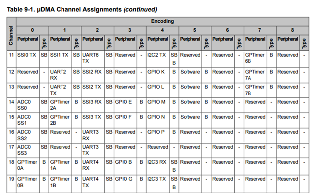
As Above image UART3 & channel 16,17 is at peripheral2

Above Image given UART0 & channel 8,9 as peripheral 0.

Comparing to UART0 , am i making mistake in configuration of UART3 Receive with uDMA or may i use same configuration ;ile UART0 receive with uDMA ? Please refer to the code and guide me in a right direction to receive data using uDMA.

  • One difference between UART0 uDMA and UART3 uDMA is that uDMA channel 8 is the default channel for UART0 RX, but uDMA channel 16 is not the default channel for UART3 RX. Therefor you must include a call to uDMAChannekAssign(UDMA_CH16_UART3RX);

  • Thank you for the reply Bob,

    Good Info, I have Included "uDMAChannekAssign(UDMA_CH16_UART3RX);" in configuration but there is no change. If that is the only issue, need to get data but no data came into my internal buffer. Am i missing something more ?

    void Init_UDMA()
    {
        //
        // Enable the uDMA controller at the system level.  Enable it to continue
        // to run while the processor is in sleep.
        //
        ROM_SysCtlPeripheralEnable(SYSCTL_PERIPH_UDMA);
        ROM_SysCtlPeripheralSleepEnable(SYSCTL_PERIPH_UDMA);
    
        //
        // Enable the uDMA controller error interrupt.  This interrupt will occur
        // if there is a bus error during a transfer.
        //
        ROM_IntEnable(INT_UDMAERR);
    
        //
        // Enable the uDMA controller.
        //
        ROM_uDMAEnable();
    
        //
        // Point at the control table to use for channel control structures.
        //
        ROM_uDMAControlBaseSet(pui8ControlTable);
    
        //
        // Enable the GPIO Peripheral used by the UART.
        //
        SysCtlPeripheralEnable(SYSCTL_PERIPH_GPIOA);
    
        //
        // Enable UART0.
        //
        SysCtlPeripheralEnable(SYSCTL_PERIPH_UART3);
    
        //
        // Enable processor interrupts.
        //
        IntMasterEnable();
    
        //
        // Configure GPIO Pins for UART mode.
        //
        GPIOPinConfigure(GPIO_PA4_U3RX);
        GPIOPinConfigure(GPIO_PA5_U3TX);
        GPIOPinTypeUART(GPIO_PORTA_BASE, GPIO_PIN_4 | GPIO_PIN_5);
    
        //
        // Initialize the UART for console I/O.
        //
        //UARTStdioConfig(3, 1000000, g_ui32SysClock);
        UARTConfigSetExpClk(UART3_BASE, g_ui32SysClock, 1000000,
                            (UART_CONFIG_WLEN_8 | UART_CONFIG_STOP_ONE |
                            UART_CONFIG_PAR_NONE));
    
        // UART9BitAddrSend(UART0_BASE, 0x00);
        //  UART9BitEnable(UART0_BASE);
    
        UARTFIFOEnable(UART3_BASE);
    
        UARTFIFOLevelSet(UART3_BASE, UART_FIFO_TX4_8, UART_FIFO_RX4_8);
    
        //
        // Enable the UART for operation, and enable the uDMA interface for both TX
        // and RX channels.
        //
        // MAP_UARTEnable(UART0_BASE);
        MAP_UARTDMAEnable(UART3_BASE, UART_DMA_RX | UART_DMA_TX);
    
        //HWREG(UART3_BASE + UART_O_CTL) |= UART_CTL_LBE;
    
        MAP_uDMAChannelAssign(UDMA_CH16_UART3RX);
        
        //
        // Put the attributes in a known state for the uDMA UART1RX channel.  These
        // should already be disabled by default.
        //
        MAP_uDMAChannelAttributeDisable(UDMA_CH16_UART3RX,
        UDMA_ATTR_ALTSELECT | UDMA_ATTR_USEBURST |
        UDMA_ATTR_HIGH_PRIORITY |
        UDMA_ATTR_REQMASK);
    
        //
        // Configure the control parameters for the primary control structure for
        // the UART RX channel.  The primary contol structure is used for the "A"
        // part of the ping-pong receive.  The transfer data size is 8 bits, the
        // source address does not increment since it will be reading from a
        // register.  The destination address increment is byte 8-bit bytes.  The
        // arbitration size is set to 4 to match the RX FIFO trigger threshold.
        // The uDMA controller will use a 4 byte burst transfer if possible.  This
        // will be somewhat more effecient that single byte transfers.
        //
        MAP_uDMAChannelControlSet(UDMA_CH16_UART3RX | UDMA_PRI_SELECT,
        UDMA_SIZE_16 | UDMA_SRC_INC_NONE | UDMA_DST_INC_16);
    
    
        MAP_uDMAChannelEnable(UDMA_CH16_UART3RX);
        MAP_uDMAChannelEnable(UDMA_CH17_UART3TX);
    
        //
        // Enable the UART DMA TX/RX interrupts.
        //
        MAP_UARTIntEnable(UART3_BASE, UART_INT_DMARX | UART_INT_DMATX);
    
        MAP_UARTEnable(UART3_BASE);
        
        //
        // Enable the UART interrupt.
        //
        MAP_UARTIntEnable(UART3_BASE, UART_INT_RX | UART_INT_RT);
    }
    
    void uDMA_Receive()
    {
    
            ROM_uDMAChannelTransferSet(
                    UDMA_CH16_UART3RX | UDMA_PRI_SELECT,
                    UDMA_MODE_BASIC,
                    (void*) (UART3_BASE + (uint16_t) (UART_O_DR & 0xFFFF)),
                    gu8Array, sizeof(gu8Array));
    
           // ROM_uDMAChannelEnable(UDMA_CH16_UART3RX);
           // ROM_uDMAChannelRequest(UDMA_CH16_UART3RX);
        
    }

  • Have you verified that UART3 is working with a simple polled routine? If you have, then export your entire project to a .zip file and attach it to this thread. I will then look at it.

  • Yes Bob,

    I have tried that and In this Process also i'm Receiving Byte by Byte when i Kept/Use a Breakpoint at Function Also Received Byte Replacing with the New Byte in My Internal Buffer(gu8Array) i uased a breakpoint at Function below

    " ROM_uDMAChannelTransferSet(
    UDMA_CH16_UART3RX | UDMA_PRI_SELECT,
    UDMA_MODE_BASIC,
    (void*) (UART3_BASE + (uint16_t) (UART_O_DR & 0xFFFF)),
    gu8Array, sizeof(gu8Array));"

    Need to get more clarity whats happening internally. Any help would be very thankful.

  • Please export your project to a .zip file and attach it.

  • Ok Bob,

    Code File.zip

    Please check and Update me Bob. Any help to resolve this issue would be very Thankful. In this we are using RS485 to Communicate with our MSP430FR2355 Customized Board.

  • There were several issues in the code you provided. I will only summarize the modifications I had to make because I do not have your hardware.

    Since I don't have a device which will respond to the packet you sent, I used loopback mode. Line 231 in main.c enables loopback mode.  I also changed the number of bytes to receive to 

      sizeof(gu8Array) >> 1u

    because each transfer was transferring two bytes.

    BC_Initial_Dummy2.zip