This thread has been locked.

If you have a related question, please click the "Ask a related question" button in the top right corner. The newly created question will be automatically linked to this question.

TMS570LS1224: CAN communication doubt

Part Number: TMS570LS1224
Other Parts Discussed in Thread: HALCOGEN,

I am a novice to CAN communication. I am using TCAN1043DQ1 transceiver and TMS570LS1224 launchpad ( using Halcogen and CCS environment.

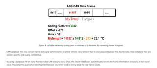
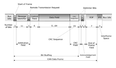
Can I get a sample code for transmitting information like given in the below image ? What are the bit fields that are essential ?

How to create a CAN database for automotive application ?

  • Hi Sakthi,

    I posted a example CCS project couple days ago.

    https://e2e.ti.com/support/interface-group/interface/f/interface-forum/1007625/tcan1043-q1-tcan1043-code-example-for-tms570-mcu?tisearch=e2e-sitesearch&keymatch=TCAN1043#

    All the bit fields in the CAN data frame picture are essential. 

    There are four types of CAN frames:

    1. Data Frame

    2. Remote Frame

    3. Error Frame

    4. Overload Frame

    The data frame is the standard CAN message, broadcasting data from the transmitter to the other nodes on the bus. A remote frame is a message by a transmitter to request data from a specific node. An error frame may be transmitted by any node that detects a bus error. Overload frames are used to introduce additional delay between data or remote frames.

    As indicated in the picture you posted. The CAN data frame is composed of seven fields: Start of frame (SOF), arbitration, control, data, CRC, ACK and end of frame (EOF). CAN message bits are referred to as “dominant” (0) or “recessive” (1). The SOF field consists of one dominant bit. All network nodes waiting to transmit synchronize with the SOF and begin transmitting at the same time. An arbitration scheme determines which of the nodes attempting to transmit will actually control the bus.

    The CAN controller will generate the SOF, CRC, EOF, CRC delimiter automatically when the CAN transmitter transmits data. You need to specify the message ID (11-bit or 29-bit), data length (DLC) (maximum is 8 bytes for classic CAN communication), and the data. If the message is not a remote frame, the RTR should be 0.  ACK is asserted by the message receiver when it receives the message. The IDE stands for extended frame ID (29-bit). 

    In my example:

    1. message ID = 123U, and it is programmed to IF1ARB register. Bit 30 =1 means that 29-bit ID (extended) is used for this message. Bit 29=1 means this message is for transmit. bit [28:0] is the message ID.

    canREG1->IF1ARB  = (uint32)0x80000000U | (uint32)0x40000000U | (uint32)0x20000000U | (uint32)((uint32)((uint32)123U & (uint32)0x1FFFFFFFU) << (uint32)0U);

    2. DLC is programmed to IF1MCTL register.

    canREG1->IF1MCTL = 0x00001000U | (uint32)0x00000800U | (uint32)0x00000000U | (uint32)0x00000000U | (uint32)8U;

    To transmit the message, you can simply call the API generated by HALCOGen:

     canTransmit(canREG1, canMESSAGE_BOX1, tx_ptr).