This thread has been locked.

If you have a related question, please click the "Ask a related question" button in the top right corner. The newly created question will be automatically linked to this question.

TM4C1290NCPDT: SSI interface in Sensor and Tiva

Guru 12165 points
Part Number: TM4C1290NCPDT
Other Parts Discussed in Thread: EK-TM4C1294XL

Hi,

I want to read data using SSI interface with TM4C1290 and sensor.

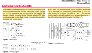
Temposonics R-Series

http://www.mtssensor.co.jp/en/products/industrial-sensors/r-seriesv.html

Is it feasible with the QSSI module "Texas Instruments Synchronous Serial Frame Format"?

"Texas Instruments Synchronous Serial Frame Format" is 16 bits, but I was concerned that the output data of the sensor is 24 to 26 bits.

If it's feasible with other QSSI, please let me know.

  • HI,

      The TM4C129 should be able to handle this. You can configure the character width to 12 bits and send two 12bits at a time for 24bits. Or configure 13bit character width and send two 13bits at a time for 26bits.  

      The QSSI module operating in Advance mode can support this. You will configure the FSSHLDFRM (FSS Hold Frame) such that the chip-select is low for the entire frame. 


  • Hi, Charles

    The SSI format of the sensor.

    (1) Is it necessary to use the Frame Hold function in order to use the above sensor?

    (2) Is it okay to recognize that the format for using this sensor is Freescale SPI Frame Format?

    (3) Is there any sample code that can be used as a reference?

    Thanks,

    Koki

  • Hi Koki-san,

    (1) Is it necessary to use the Frame Hold function in order to use the above sensor?

    I think so. If you don't do the hold, then the Fss (chip-select) signal will be de-asserted at the end of the frame. For example, if you are doing two back-to-back of 12-bits then at the end of a 12-bit frame, the Fss will go high and then go low for the next 12-bit transmission. Note that you don't need to use Fss. You could easily use a GPIO for the chip-select. 

    (2) Is it okay to recognize that the format for using this sensor is Freescale SPI Frame Format?

    Yes, it is the preferred format. 

    (3) Is there any sample code that can be used as a reference?

    Please refer to C:\ti\TivaWare_C_Series-2.2.0.295\examples\boards\ek-tm4c1294xl\ssi_quad_mode example. Look at MAP_SSIAdvFrameHoldEnable() is called to enable the frame hold and  MAP_SSIAdvDataPutFrameEnd() de-assert the Fss signal. 

  • Hi, Charles

    Thank you for your answer.

    I have a new question from your answer, so I will ask you a question.

    Specifically, the following sensors are used.

    https://www.temposonics.com/portals/MTS_Sensors/documents/R-Series/Data_Sheet_R-Series_RP_RH_SSI_550989_EN.pdf


    (1) The above sensor does not seem to have Fss (Chip Select). Is it possible to communicate with SSI?

      Is GPIO (Chip Select) not required for 1 (MCU) vs 1 (Sensor) communication? 

    You could easily use a GPIO for the chip-select. 


    (2) Is the transfer of SSI communication "continuous back-to-back transfers" described in UG?


    (3) If the data length of the sensor is 25bit, 12bit + 13it will be transmitted continuously. Is the above understanding correct?


    Thanks,

    Koki

  • Hi,

    (1) The above sensor does not seem to have Fss (Chip Select). Is it possible to communicate with SSI?

    If your slave device does not need the chip select then you just leave it out. Some devices require chip-select and some don't. In your case, you just need CLK and DATA according to the UG. 

    (2) Is the transfer of SSI communication "continuous back-to-back transfers" described in UG?

    I'm not familiar with the sensor device. You should consult the sensor vendor for confirmation. But according to the UG, it does not support continuous back-to-back transfers. From what I can see, you need a minimum of 16uS of pause before you can start the next transfer. Again, it is your sensor, I will suggest you consult sensor vendor. From the MCU point of view, it can do continuous transfers. 

    (3) If the data length of the sensor is 25bit, 12bit + 13it will be transmitted continuously. Is the above understanding correct?

    This is a very odd character length. You need to first do a 12-bit transfer and then you will need to reprogram the SSI module character length for 13-bit next. There will be some delay between the 12bits and 13bits. You need to check with your sensor vendor how much delay is allowed. 

  • Hi, Charles

    I would like to confirm (2) and (3) with the Sensor vendor.

    Regarding (1), please let me check it just in case.

    Please tell me how to connect the Fss pin when it is not in use.

    Thanks,

    Koki

  • Hi,

      As I just said in my last reply, you don't need to connect the Fss if your sensor device doesn't need it. You just don't configure the Fss pin on the MCU. You can repurpose the Fss pin for GPIO or just leave it open. 

  • It is the first time.
    I am developing "SSI-sensor-2ch-IF BOARD".
    "koki" asked you a question on my behalf.

    I also have a question.

    TM4C1290.
    I want to use the same SSI-module for CLK output and DATA receiving for one sensor.
    Is it possible?
    for that purpose
    Q1.
    Is the argument "ui32Mode" of the function "void SSIConfigSetExpClk ()" "SSI_MODE_MASTER"?
    Q2.
    Is the argument "ui32Mode" of the function "MAP_SSIAdvModeSet ()" "SSI_ADV_MODE_LEGACY"?

    please tell me.
    INO
    ----
    to koki
    arigatougozaimasita.
    INO

  • Hi,

    I want to use the same SSI-module for CLK output and DATA receiving for one sensor.
    Is it possible?

    Yes, it is possible. You just don't connect the TX pin. The MCU (master) will just drive the CLK and receive data from the RX pin.

    Q1.
    Is the argument "ui32Mode" of the function "void SSIConfigSetExpClk ()" "SSI_MODE_MASTER"?

    You are correct.

    Q2.
    Is the argument "ui32Mode" of the function "MAP_SSIAdvModeSet ()" "SSI_ADV_MODE_LEGACY"?

    Yes, I think you can use the SSI_ADV_MODE_LEGACY. Earlier I suggested to use Advance mode. Reading the datasheet again, please note that the Advance mode will only support 8-bit transfer. Therefore, if you want to transfer 24bits, then you can break into three 8-bit transfers. If this is the use case, then you will pick SSI_ADV_MODE_READ_WRITE. However, if you want to do two 12-bit transfers then you need to stay with SSI_ADV_MODE_LEGACY which is the default setting. 

  • I'll try.
    Thanks,
    INO

  • After reading through this thread, some things stand out.

    One -- the data sheet for the sensor shows that each data bit is driven with the rising edge of the clock. "SPI" generally drives output bits with the falling edge of the clock and those bits are captured on the rising edge of the clock. You will need to make sure the edge of the clock on which the TI USART or SPI module captures the bits is correct!

    Two -- the sensor data sheet doesn't give any setup and hold timing. Its only timing is baud rate as a function of cable length. So that's another reason why it's prudent to capture the bits on the falling edge of the clock.

    Three -- the number of bits in the data frame can be non-standard, 25 or 26 bits in addition to 24. Also the data can be binary or Gray code. Both of these are dependent on what exact part is ordered.

    Now if I were to implement this in a TM4C, I wouldn't bother with trying to make the micro's sync serial ports work. I recently did up an interface to that cruddy HX711 strain gauge amplifer/digitizer chip, and that has a 24 (or 25 or 26) bit serial interface which looks a whole lot like this sensor's interface.

    I came up with a "better" bit-bang. It uses two pins. The data pin is a GPIO configured as an input.

    I generated the clock with a Timer CCP output driven by PWM. The timer load value sets the period of the clock. The timer match value sets the duty cycle, so if the match value is half of the timer load value you get 50% duty cycle.

    Here's the clever part. Configure the timer to interrupt on the falling edge of the timer output. That's the edge of the clock on which you want to capture an input bit.

    Set up another timer to pace the sensor reads. When that timer expires, enable the clock timer. This starts the shift process.

    In the clock timer ISR, you keep track of the number of bits you've shifted in, as well as a shift register for the incoming bits. For each incoming bit, shift the register left, read the data bit GPIO, and OR that bit with the shift register to update the shifter. If you've just read the last bit in the data frame, set a global flag your main loop can read, and disable the PWM timer so the clock stops. The main loop can read the result at its leisure.

    All of this is a lot easier than trying to force the SSI peripherals to do something nonstandard and weird. Good luck.

  • Hi, Andy
    Thanks for your good idea!

    The CLK output of the CPU and the CLK input of the sensor are electrically inverted.
    Capture with the red line.
    However, the capture of "1" is ignored because there is no data.
    Since the sensor data length this time is 24 / 25bit
    I'm going to read with setting 13bitX 2 times = 26bit.
    I'll debug it soon.
    INO