This thread has been locked.

If you have a related question, please click the "Ask a related question" button in the top right corner. The newly created question will be automatically linked to this question.

TMS570LS1224: Loopback Tests - N2HET

Part Number: TMS570LS1224
Other Parts Discussed in Thread: HALCOGEN

Hi,

I am trying to do analog  loop back tests for N2HET.

What I am trying to do is:

1. Generated a PWM on HET[12]

2. Connected HET[12] and HET[13] in analog loop back mode

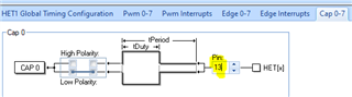
3. Configured CAP0 to measure the PWM signal on HET[13]  

4. Measured the PWM dutycycle and period using the function capGetSignal

But I am unable to get the captured signals pwm and dutycycle. Is there any thing I am doing wrong ?

A code snippet of what I am trying to do is posted:

void test_analog_n2het()

{

/* configure LBPDIR[12/13] = 1, HR structure 12 will be output and
* HR structure 13 will be input*/
/* configure LBPTSTENA[16-19] = 0xAh to enable loop back test*/
hetREG1->LBPDIR |= 0x000A0040U;

/* configure LBPSEL[12/13] = 1, HR structures 12 & 13 will be internally connected in loop
back mode.*/
/* configure LBPTYPE[12/13] = 1. This will configure HR structure 12 - 13 in analogue
* loop back mode */
hetREG1->LBPSEL |= 0x00400040U;

}

void measure_cap_signal()

{

capGetSignal(hetRAM1, 0U, &het_signal_capture);
printf("The PWM of captured signal : %f\n", het_signal_capture.period);

}

I have noted the PWM generation on HET[12] is fine. 

Can any one please tell me what is going wrong ? 

Regard

S

  • Hi SamS,

    Please double check if LBPDIR and LBPSEl are programmed correctly. 

    The default value of LBPDIR[19:16] is 0x5, and your code sets bit 17 and bit 19 (|0xA), so the LBPDIR[19:16] becomes 0xF which means the loopback is disabled.

    It's better to use the instructions below for loopback test:

    hetREG1->LBPDIR = 0x000A0040U;

    hetREG1->LBPSEL = 0x00400040U;

  • Hi.

    I realised this just a moment ago when I was debugging the register contents . I was testing with the following code. It has the same setting of the register you just recommended. 

    void test_n2het_configure_loopback( void )
    {

    /* configure LBPDIR[12/13] = 1, HR structure 12 will be output and
    * HR structure 13 will be input*/


    /* configure LBPTSTENA[16-19] = 0xAh to enable loop back test*/


    hetREG1->LBPDIR = 0x000A0040U;

    /* configure LBPSEL[12/13] = 1, HR structures 12 & 13 will be internally connected in loop
    back mode.*/


    /* configure LBPTYPE[12/13] = 1. This will configure HR structure 12 - 13 in analogue
    * loop back mode */


    hetREG1->LBPSEL = 0x00400040U;

    }

    void test_n2het_get_captured_signal(void)
    {
    capGetSignal(hetRAM1, 0U, &het_signal_capture);
    printf("The Period of captured signal : %lf\n", het_signal_capture.period);
    printf("The Duty of captured signal : %ld\n", het_signal_capture.duty);
    }

    The output on console is as (configured to capture the PWM on HET[13] by configuring loopback form HET[12] ):

    The Duty of captured signal : 133
    The Period of captured signal : 375.200000

    which is not the expected ones since The PWM I am generating on HET[12] is with a period of 1000 and Dutycycle 500(50%)

  • Which ecap channel is assigned to NHET1[13]? 

    capGetSignal(hetRAM1, 0U, &het_signal_capture); ---> you use ecap channel 0 to read the period and duty cycle.

  • Yes , I have assigned CAP0 signal as shown :  

    1. Not sure whether I should I use an interrupt function to call capGetSignal(hetRAM1, 0U, &het_signal_capture)

    I am currently running it in  1 ms  scheduler loop 

    2. I have configured HET[13] as an input port in HRshare as shown : 

  • Hi,

    The loop back direction is selected by setting the LBPDIR register which is independent of the HETDIR register setting. 

    You don't have to use the interrupt service routine to read the period and duty cycle of the input PWM signal if the input PWM is a continuous signal. 

    I am currently running it in  1 ms  scheduler loop 

    Is the PWM disabled on HET1[12] after 1ms? You said the PWM period is 1000us (1ms), so the NHET1[12] only generate 1 PWM pulse. 

    BTW, do you use the code generated by HALCoGen without any change?

    The original ecap capture code uses HR share feature. 

    Please modify the code of instruction 26 of "static const hetINSTRUCTION_t het1PROGRAM[58U]" in het.c as below and try again:

    /* PCNT: Capture Period 0
    * - Instruction = 26
    * - Next instruction = 27
    * - Conditional next instruction = na
    * - Interrupt = na
    * - Pin = 13 + 1  --> change to 13
    */
    {
    /* Program */
    0x00036EA0U | (uint32)((uint32)0U << 6U) | (uint32)((0U) + 13U),
    /* Control */
    0x00000000U,
    /* Data */
    0x00000000U,
    /* Reserved */
    0x00000000U
    },

  • Hi,

    Thank you very much for your support. Now it works:

    Here is the log. 

    The Period of captured signal : 1000.000000
    The Duty of captured signal : 49

    Would like to know what was the issue. Why we need to correct the het.c file. Was it something wrong on my side ?

  • Hi SamS,

    The N2HET supports high resolution and standard resolution. The N2HET instruction such as PCNT used for ECAP has 7-bit HR data field. For standard resolution, the 7-bit HR data is ignored. For high resolution, the 7-bit HR data can measure high resolution delays (HR delay). But the restriction is that only one instruction is allowed to operate in High Resolution mode (for 1 N2HET pin). PCNT can be used to measure the PWM period or pulse duration (duty-cycle). 

    If the PWM is feed to N2HET1[13] pin, one PCNT is used to measure period, another PCNT is to measure the duty-cycle. If HR share is not enabled, only one PCNT can operate in high resolution mode. The example code generated by HALCoGen enables the HR share, both PCNT instructions for period and duty-cycle operate in high resolution mode.

    Regarding HR share structure, please refer to 21.2.5.5 in TRM.

  • Hi ,

    Thank you for your reply. 

    Sorry, I could only understand it to some extend.

    1. So it it that since the HR share is enabled in Halcogen it share the same pin. So in  generated code we need two PCNT instructions to measure period and duty from the same pin, here Pin 13. So we configured one more PCNT instruction as you have suggested above to compute the duty for the same pin. Earlier when it was not working there was only one PCNT instruction computing the period. 

    Is this understanding correct ?

    2. Also does the modification to 0x00036EA0U is required. It was working without this modification. What is the significance of 0x00036EA0U?

    Regards

    Sam

  • Hello Sam,

    1. HR share is enabled in HALCoGen generated example code, the PCNT instruction for duty-cycle uses the HR structure of pin 12 (even), and the PCNT instruction for period uses the HR structure of pin 13 (odd pin). The PWM signal for bother HR structures is from pin 12 (even pin). 

    In analog loopback configuration, HR share is disabled. Only one HR structure (pin 13 in your setting) is used for both duty-cycle and period. This is why I change the pin number in the 2nd PCNT instruction to 13.

    2. This is to disable the HR in the 2nd PCNT instruction. This change is not required since the high resolution pin structures respond only to the first instruction that is executed matching their pin number with hr_lr=HIGH. Subsequent instructions are ignored by the high resolution pin
    structure for the remainder of the loop resolution period.

  • Thank you for excellent support and clarification ! So in normal scenario if there was no loopback, Pin 13 and Pin 13+1 would have been used for duty cycle and period measurement since as per my setting (I have assigned PIN13 in my case to CAP0)  isn't it ?

  • The N2HET HR structure pair: N2HET[n] and N2HET[n+1], where n is a even number. When HR input of N2HET[n] and N2HET[n+1] are shared, the measure pin is N2HET[n].

    In your example, N2HET1[12] and N2HET1[13] are one pair, the input signal should be connected to N2HET1[12]. If HR share for N2HET1[12]/N2HET1[13] is enabled, N2HET1[12] HR structure and N2HET1[13] HR structure share the same pin N2HET1[12] rather than N2HET1[13].

  • Thank you for your clarification and support.