This thread has been locked.

If you have a related question, please click the "Ask a related question" button in the top right corner. The newly created question will be automatically linked to this question.

TM4C1294KCPDT: I2C SCL frequency

Part Number: TM4C1294KCPDT

Hello team,

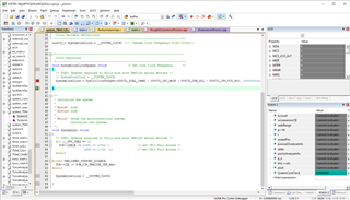
My customer uses the device with external 16MHz oscillator and 120MHz system clock.

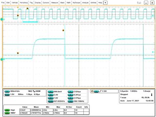
And customer uses both Fast Mode(400kbps) and Fast Mode Plus(1000kbps) I2C.

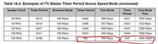
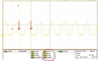
Customer measured clock frequency of the I2C signal, however what they observed is 387kHz for Fast mode and 922kHz for Fast mode plus.

Could you let me know typical(or target) SCL frequency for the conditions?

It would be helpful If its variation data is also available.

Best regards,

  • First, you failed to mention if the customer is using the I2C in Master or Slave mode. Assuming the TM4C1294 is the master, the SCL frequency will be as accurate as the clock source. Using an external 16MHz crystal should make it very accurate. So here are the possible reasons I think your customer may be measuring a different frequency.

    1) The PLL is not properly configured and the system clock is not 120MHz (I don't think it is likely, but should be double checked)

    2) The slave device is doing clock stretching

    3) The customer is measuring the SCL clock with a frequency meter or the frequency function of an oscilloscope. The I2C clock is not continuous, and may remain high between transfers. This causes the average clock rate to be measured lower than the clock rate for each bit. Have the customer measure the clock period of a bit in the middle of a transmission and compute the frequency from the period.

  • Hello Bob-san,

    Thank you for your comment.

    >First, you failed to mention if the customer is using the I2C in Master or Slave mode.

    Sorry for missing information. Customer uses TM4C1294 as master as you assumed.


    I got waveform from customer. please see attached below for fast mode SCL.

    I don't think (2) slave's clock stretching or (3) measurement method is a reason of the frequency difference.

    Regarding (1) PLL configuration, customer observes correct frequency of SPI clock(TM4C1294 is master) as expected. so system clock seems properly configured. Customer will confirm this just in case.


    I had customer confirm I2C glitch filter setting but MTPR register's PULSE is configured as zero.

    I would appreciate it if you could suggest other possible reason.

    Best regards,

  • If it is not clock stretching, and it is not the measurement technique, then it is most likely a configuration issue or crystal issue. You mention that they are using an external 16MHz crystal. Can they measure the frequency of the external crystal?  It should be measured on the side connected to OSC1, pin 89.

    How do they configure the PLL? Is it:

        g_ui32SysClock = SysCtlClockFreqSet((SYSCTL_XTAL_16MHZ |
                                           SYSCTL_OSC_MAIN |
                                           SYSCTL_USE_PLL |
                                           SYSCTL_CFG_VCO_240), 120000000);
    

    This example is only valid for TivaWare version 2.2.0.295. If they are not using this version, which version are they using?

  • Hello Bob-san,

    Thank you for your comment. Customer measured OSC1, pin89 and provided below waveform.

    It runs with 16MHz.(Customer mentioned the waveform rounding may be due to probe capacitance and actual waveform may be better than it)

    Could you check this waveform will cause the I2C frequency difference?


    Regarding PLL configuration, customer is now confirming with SW engineer and will give us feedback.

    Best regards,

  • The shape of the waveform does not concern me. The frequency looks correct. I will wait for the PLL configuration information.

  • Hello Bob-san,

    Thank you for your confirmation of the ext. 16MHz.

    Customer confirmed PLL configuration below and 120MHz system clock is made from the ext. 16MHz. Return value is 120MHz so customer thinks there is no problem.

    They are using Tivaware version 2.2.0.295.

    Please let me know if you notice anything.

    Best regards,

  • Unfortunately I don't have hardware with a TM4C129 device running off of a 16MHz external crystal. Would you ask them to provide the value in the : I2C Master Timer Period (I2CMTPR) register after the I2C is configured?

  • Hello Bob-san,

    Customer confirmed and gave below picture. I2C2 is for 1M(0x5) and others are for 400k(0xE).

    Best regards,

  • Those are the correct values for the master clock time period register. The baud rate is a digital divide of the system clock. It will be as accurate as the system clock. There is no analog skew of the frequency in the clock generation. The only thing I can think of is that even though the SysCtlClockFreqSet() function is correctly selecting the main oscillator, somewhere the PIOSC is switched to the PLL clock source. This can be checked by looking at the value in the RSCLKCFG register. The PLLSRC bits, 27-24, should be equal to 0x3.

  • Hello Bob-san,

    Customer confirmed RSCLKCFG-PLLSRC bit and MOSC is the PLL clock input source. Please see below image.


    Customer also removed slave devices and confirmed I2C clock, but customer still sees different clock frequency.

    Could you please let me know if there are other possibility to cause the frequency difference?

    Best regards,

  • I still don't see where the discrepancy can be. I don't have hardware with a 16MHz crystal but I will measure the I2C clock frequency with 120MHz system clock and a 25MHz crystal next week when I am in the office. I am currently still working from home and do not have access to an accurate scope.

  • Hello Bob-san,

    I would appreciate it if you could check the behavior at your side when you comes to office.

    Best regards,

  • Hello Bob-san,

    Did you have a chance to confirm the behavior?

    Best regards,

  • I have been able to duplicate what your customer is seeing. It is clock stretching, but not from the slave. The discrepancy in period is caused by the rise time of the pullup resistor. To the master device, the time between when it releases the clock, and when the pullup resistor brings the clock line to Vih looks like clock stretching and will increase the clock low period. You can verify this by increasing the resistance of the pullup resistor and you will see the SCL period increase. 

  • Hello Bob-san,

    Thank you for the confirmation.

    I understand it is clock stretching by Master. How can we remove the clock stretching? If reducing the resistance of pullup can correct the SCL frequency, could you let me know appropriate resistance value for pullup? 

    Best regards,

  • The clock stretching cannot be removed. It is inherent to the I2C protocol. It can be minimized with strong pullup resistors, but that increases the power consumption. Is the customer having difficulty communicating at 387KHz, or is he just curious as to the reason for the discrepancy?

  • Hello Bob-san,

    Thank you for the information. I understand the clock stretching cannot be removed.

    Customer wanted to know the reason why it shows different frequency from datasheet. I will tell this to customer and confirm if there is any concern on the clock speed. When I get any specific concern I will get back to you then.

    Best regards,

  • Hello Bob-san,

    I confirmed with customer that there is no special concern on lower I2C frequency because they don't see any issue by it.

    They would like to understand below.

    • Is the purpose of the clock stretching by master to keep communication robust by stretching clock low period to relax timing margin even in case of rounded rising edge due to hardware configuration?
    • Do you have reference information how long rise time will lengthen how long clock low period?

    Best regards,

  • Is the purpose of the clock stretching by master to keep communication robust by stretching clock low period to relax timing margin even in case of rounded rising edge due to hardware configuration?

    I cannot say that is part of the original intent or not. It is true that it will stretch the low time more for slower rise time of the clock. It is inherent to the design of the clock stretching circuit that it will hold off counting the clocks for the high period until it sees a high at the SCL pin. It cannot tell if the delay between when the SCL open drain driver turns off to when the level on the SCL pin turns into a high is caused by the resistor-capacitor delay, or caused by a slave actively holding the SCL line low.

    Do you have reference information how long rise time will lengthen how long clock low period?

    It is a function of three things, the strength of the pullup resistor, the capacitance on the SCL net and the VIh threshold of the SCL pin. That threshold will be between 0.5V and 2.4V, typically close to 1.5V but does vary with process, temperature and supply voltage.

  • Hello Bob-san,

    Customer observed SCL frequency changes along with pull-up resistor as you mentioned.

    Pull-up resistor[ohm] 470 1.1k 2.4k 4.7k
    Cycle time[us] 1.034 1.052 1.084 1.138
    Frequency[kHz] 967.118 950.5703 922.5092 878.7346
    High time[ns] 436 450 484 546
    Low time[ns] 592 592 592 590
    Rise time[ns]
    (1.14V~2.14V)
    6.4 17 36 80

    What customer see is SCL low period is fixed and High period is changing along with pull-up resistor, while you said Low period will change.

    Is the customer observation correct as the device's clock stretching?

    Best regards,

  • Yes, this is clock stretching caused by the rise time of the pullup resistor. I refer to it as the low period being stretched because the master I2C circuit in the device considers it low period until the SCL line rises to Vih. In this case it is the rise time that is actually stretched as the pullup resistance is increased. The time that the master holds SCL low is constant. The time that SCL is above Vih until it goes low again will be constant. The time between when SCL is released and when it hits Vih is what increases.