


Good morning. I am facing some problems with the I2C master interface on MSP432E401Y, writing to AT24C64D EEPROM.
1) When doing a single random write, MSP432E401Y correctly sends
-START, device address, MS address byte, LS address byte, data byte, followed by a STOP.
2) When doing two or more random writes after each other, MSP432E401Y sends
-START, device address, MS address byte, LS address byte, data byte, followed by a STOP.
then
-START, device address, STOP.
I. e. for random write # 2, MS address byte, LS address byte, data byte are simply missing.
It appears that in general, every second random write suffers from missing MS address byte, LS address byte, data byte.
If I take seconds-long break between each random write, (blinking an LED for one second) it appears to write all bytes correctly. I have tested this with e. g. 256 bytes and a LED blink between each write.
In the plots, Ch1 = SCLK, Ch2 = SDA, Ch3 = PD2_PULSE(pulses), added to easier trace the transmission progress.
at24c64d_6_1.jpg shows one random write. It is OK.
at24c64d_6_2.jpg shows two random writes. #1 is OK. #2 has only the device address, no memory address, no data, they are simply skipped. From Ch3 you see that the code is executed as it actually executes PD2_PULSE(4) and PD2_PULSE(1). After device address there are four pulses PD2_PULSE(4) to make viewing easier.
I have the TPS23861PWR attached on the same bus. I2C communication works without a problem, although I only use it to read one and one byte.
What could be causing the I2C master to send only START, device address, STOP for every second random write?
Parts of the code attached.
BR
Reidar Gjerstad

This plot shows one random write: START, device address, MS address byte, LS address byte, data byte, followed by a STOP. Pink Ch3 = PD2_PULSE(pulses).
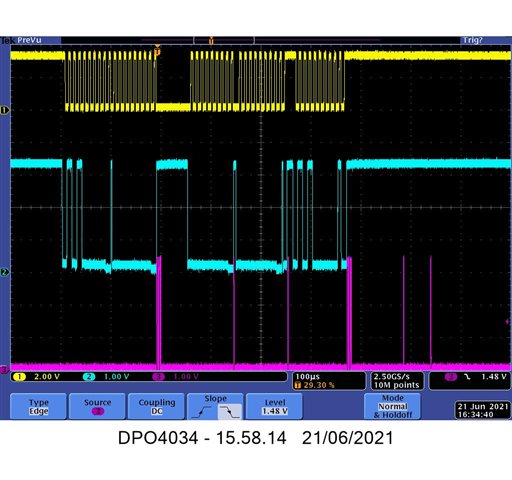
This plot shows two random writes: # 1 is OK. For #2 the master sends only the device address. No data is sent after the slightly wider PD2_PULSE(4);
void i2c_write_linear()
{
uint8_t data = 0;
uint16_t addr = I2C_ADDR_START;
UARTprintf("Writing %d memory locations to i2c:\n\r", I2C_ADDR_LOCATIONS);
while ( addr < (I2C_ADDR_START + I2C_ADDR_LOCATIONS ) )
{
data = (uint8_t)addr;
if (DEBUG)
{
UARTprintf("Write @0x%x 0x%x\n\r", addr, data);
}
i2c_rand_write(addr, data);
//LED0_BLINK(1);
addr++;
}
}
void i2c_rand_write(uint16_t address, uint8_t data)
{
// Set slave address and r/w bit
// rx bit
MAP_I2CMasterSlaveAddrSet(I2C0_BASE, I2C_SLAVE_ADDR, false);
// Set MS Address Byte
MAP_I2CMasterDataPut(I2C0_BASE, (uint8_t)(address >> 8));
// Send slave address and MS address Byte
MAP_I2CMasterControl(I2C0_BASE, I2C_MASTER_CMD_BURST_SEND_START);
check_master_busy();
PD2_PULSE(4);
// Set second address Byte
MAP_I2CMasterDataPut(I2C0_BASE, (uint8_t)address);
check_master_busy();
// Send second address Byte
MAP_I2CMasterControl(I2C0_BASE, I2C_MASTER_CMD_BURST_SEND_CONT);
check_master_busy();
PD2_PULSE(1);
// Set data Byte
MAP_I2CMasterDataPut(I2C0_BASE, data);
// Send data Byte and Stop
MAP_I2CMasterControl(I2C0_BASE, I2C_MASTER_CMD_BURST_SEND_FINISH);
check_master_busy();
PD2_PULSE(1);
}
After each operation I check the busy-bit:
//
// BUSYBIT:
// After the CPU starts a transaction, up to 60% of the I2C clock period is required before the
// BUSY bit is set. Therefore, a delay is required before reading this bit:
//
#define I2CMCS_BUSYBIT_DLY 2000 //Delay before reading the master busy bit
void check_master_busy()
{
MAP_SysCtlDelay(I2CMCS_BUSYBIT_DLY);
while (I2CMasterBusy(I2C0_BASE));
}
I have initialized the I2C master according to document SLAA776:
void setup_i2c()
{
//
// Enable the I2C0 GPIOs
// I2C0SCL = PB2, pin 91
// I2C0SDA = PB3, pin 92
//
MAP_SysCtlPeripheralEnable(SYSCTL_PERIPH_GPIOB);
//
// Wait for the Peripheral to be ready for programming
//
while(!MAP_SysCtlPeripheralReady(SYSCTL_PERIPH_GPIOB));
/* Configure Pins for I2C0 Master Interface */
MAP_GPIOPinConfigure(GPIO_PB2_I2C0SCL);
MAP_GPIOPinConfigure(GPIO_PB3_I2C0SDA);
MAP_GPIOPinTypeI2C(GPIO_PORTB_BASE, GPIO_PIN_3);
MAP_GPIOPinTypeI2CSCL(GPIO_PORTB_BASE, GPIO_PIN_2);
/* Stop the Clock, Reset and Enable I2C Module in Master Function */
MAP_SysCtlPeripheralDisable(SYSCTL_PERIPH_I2C0);
MAP_SysCtlPeripheralReset(SYSCTL_PERIPH_I2C0);
MAP_SysCtlPeripheralEnable(SYSCTL_PERIPH_I2C0);
/* Wait for the Peripheral to be ready for programming */
while(!MAP_SysCtlPeripheralReady(SYSCTL_PERIPH_I2C0));
//
// Wait for the I2C0 module to be ready.
//
while(!MAP_SysCtlPeripheralReady(SYSCTL_PERIPH_I2C0))
{
}
//
// Initialize and Configure the Master Module
//
MAP_I2CMasterInitExpClk(I2C0_BASE, g_ui32SysClock, false);
}
#include "project.h"

// Bits 6..0. Note that it will be left shifted by uC
#define I2C_SLAVE_ADDR      0b1010000
#define I2C_ADDR_START      0x0
#define I2C_ADDR_END        256
#define I2C_ADDR_LOCATIONS  1//8192
#define I2C_ADDR_MAX        8192
#define PRINT_DATA          0
#define SEPARATORS          5
#define DEBUG               1
extern uint8_t debug;

void test_i2c_mem()
{
    hor_bar();
    UARTprintf("Testing I2C memory AT24C64D...\n\r");
    //erase_mem();
    i2c_write_linear();
    //i2c_verify_linear();
}

void erase_mem()
{
    uint16_t addr;
    UARTprintf("Erasing I2C memory...\n\r");
    for (addr = 0; addr < (I2C_ADDR_START + I2C_ADDR_LOCATIONS); addr++)
        i2c_rand_write(addr, 0xFF);
    UARTprintf("Done!\n\r");
}

void print_separators(uint8_t separators)
{
    uint8_t i;
    for (i = 0; i< separators; i++)
        UARTprintf(".");
}

void i2c_rand_test()
{
    uint16_t addr;
    uint8_t data;
    for (addr = 0; addr < 16; addr++)
    {
        data = addr;
        UARTprintf("Write 0x%x 0x%x\n\r", addr, data);
        i2c_rand_write(addr, data);
        data = i2c_rand_read(addr);
        UARTprintf("Read  0x%x 0x%x\n\r", addr, data);
    }
}

void i2c_write_linear()
{
    uint8_t data = 0;
    uint16_t addr = I2C_ADDR_START;
    UARTprintf("Writing %d memory locations to i2c:\n\r", I2C_ADDR_LOCATIONS);
    while ( addr < (I2C_ADDR_START + I2C_ADDR_LOCATIONS ) )
    {
        data = (uint8_t)addr;
        if (DEBUG)
        {
            UARTprintf("Write @0x%x 0x%x\n\r", addr, data);
        }
        i2c_rand_write(addr, data);
        //LED0_BLINK(1);
        addr++;
    }
}

void i2c_read_linear()
{
    uint16_t addr = I2C_ADDR_START;
    UARTprintf("Reading %d bytes from i2c:\n\r", I2C_ADDR_LOCATIONS);
    //while ( addr < I2C_ADDR_LOCATIONS)
    while ( addr < (I2C_ADDR_START + I2C_ADDR_LOCATIONS ))
    {
        if (DEBUG)
        {
            UARTprintf("Read  @ 0x%x 0x%x\n\r", addr, i2c_rand_read(addr));
        }
        else
        {
            // Update pbar for every tenth address
            if ((addr % 20 == 0) || addr == (I2C_ADDR_LOCATIONS-1))
                pbar(addr+1, I2C_ADDR_LOCATIONS);
        }
        addr++;
    }
    UARTprintf("\n\rDone!\n\r");
}

uint16_t i2c_verify_linear()
{
    uint16_t addr = I2C_ADDR_START, error = 0;
    uint8_t data = 0;
    UARTprintf("Verifying %d memory locations from i2c.:\n\r", I2C_ADDR_LOCATIONS);
    while ( addr < (I2C_ADDR_START + I2C_ADDR_LOCATIONS ) )
    {
        data = i2c_rand_read(addr);
        if (DEBUG)
        {
            UARTprintf("Read @ 0x%x 0x%x ", addr, data);
        }
        if ((addr % 256) != data)
        {
            error++;
            UARTprintf("ERROR!");
        }
        UARTprintf("\n\r");
        /*
        else
        {
            // Update pbar for every tenth address
            if ((addr % 10 == 0) || addr == I2C_ADDR_LOCATIONS)
                pbar(addr+1, I2C_ADDR_LOCATIONS);
        }
        */
        addr++;
    }
    UARTprintf("\n\rDone!");
    return error;
}

/*
// KEEP! This is the original!
// rx = receive
void i2c_rand_write(uint16_t address, uint8_t data)
{
    // Set slave address and r/w bit
    //                                                   rx flag
    MAP_I2CMasterSlaveAddrSet(I2C0_BASE, I2C_SLAVE_ADDR, false);
    // Set MS Address Byte
    MAP_I2CMasterDataPut(I2C0_BASE, (uint8_t)(address >> 8));
    MAP_I2CMasterControl(I2C0_BASE, I2C_MASTER_CMD_BURST_SEND_START);
    check_master_busy();
    // Set second address Byte
    MAP_I2CMasterDataPut(I2C0_BASE, (uint8_t)address);
    // Send second address Byte
    MAP_I2CMasterControl(I2C0_BASE, I2C_MASTER_CMD_BURST_SEND_CONT);
    check_master_busy();
    // Set data Byte
    MAP_I2CMasterDataPut(I2C0_BASE, data);
    // Send data Byte and Stop
    MAP_I2CMasterControl(I2C0_BASE, I2C_MASTER_CMD_BURST_SEND_FINISH);
    check_master_busy();
}
*/

// rx = receive
void i2c_rand_write(uint16_t address, uint8_t data)
{
    // Set slave address and r/w bit
    //                                                   rx bit
    MAP_I2CMasterSlaveAddrSet(I2C0_BASE, I2C_SLAVE_ADDR, false);
    // Set MS Address Byte
    MAP_I2CMasterDataPut(I2C0_BASE, (uint8_t)(address >> 8));
    // Send slave address and MS address Byte
    MAP_I2CMasterControl(I2C0_BASE, I2C_MASTER_CMD_BURST_SEND_START);
    check_master_busy();
    PD2_PULSE(4);
    // Set second address Byte
    MAP_I2CMasterDataPut(I2C0_BASE, (uint8_t)address);
    check_master_busy();
    // Send second address Byte
    MAP_I2CMasterControl(I2C0_BASE, I2C_MASTER_CMD_BURST_SEND_CONT);
    check_master_busy();
    PD2_PULSE(1);
    // Set data Byte
    MAP_I2CMasterDataPut(I2C0_BASE, data);
    // Send data Byte and Stop
    MAP_I2CMasterControl(I2C0_BASE, I2C_MASTER_CMD_BURST_SEND_FINISH);
    check_master_busy();
    PD2_PULSE(1);
}

// rx = receive
void i2c_rand_write2(uint16_t address, uint8_t data)
{
    // Dummy write sets the address pointer
    // The internal data word address counter maintains
    // the last address accessed during the last read or write
    // operation, incremented by one
    i2c_dummy_write(address);
    check_master_busy();
    PD2_PULSE(1);
    // Set data Byte
    MAP_I2CMasterDataPut(I2C0_BASE, data);
    // Send data Byte and Stop
    MAP_I2CMasterControl(I2C0_BASE, I2C_MASTER_CMD_BURST_SEND_FINISH);
    check_master_busy();
    PD2_PULSE(1);
}

uint8_t i2c_rand_read(uint16_t address)
{
    uint8_t data_read;
    // Dummy write sets the address pointer
    // The internal data word address counter maintains
    // the last address accessed during the last read or write
    // operation, incremented by one
    i2c_dummy_write(address);
    check_master_busy();
    // Set slave address and r/w bit
    //                                                   rx flag
    MAP_I2CMasterSlaveAddrSet(I2C0_BASE, I2C_SLAVE_ADDR, true);
    check_master_busy();
    // Send slave address and read byte
    MAP_I2CMasterControl(I2C0_BASE,  I2C_MASTER_CMD_SINGLE_RECEIVE);
    check_master_busy();
    data_read = MAP_I2CMasterDataGet(I2C0_BASE);
    PD2_PULSE(2);
    return data_read;
}

void i2c_dummy_write(uint16_t address)
{
    // Set slave address and r/w bit
    //                                                   rx flag
    MAP_I2CMasterSlaveAddrSet(I2C0_BASE, I2C_SLAVE_ADDR, false);
    // Set MS Address Byte
    MAP_I2CMasterDataPut(I2C0_BASE, (uint8_t)(address >> 8));
    MAP_I2CMasterControl(I2C0_BASE, I2C_MASTER_CMD_BURST_SEND_START);
    check_master_busy();
    // Set second address Byte
    MAP_I2CMasterDataPut(I2C0_BASE, (uint8_t)address);
    // Send second address Byte
    MAP_I2CMasterControl(I2C0_BASE, I2C_MASTER_CMD_BURST_SEND_CONT);
    check_master_busy();
    //
    // NO data bytes after this because it is a dummy write
    //
}
#include "project.h"

//
// BUSYBIT:
// After the CPU starts a transaction, up to 60% of the I2C clock period is required before the
// BUSY bit is set. Therefore, a delay is required before reading this bit:
//
#define I2CMCS_BUSYBIT_DLY  2000 //Delay before reading the master busy bit

void check_master_busy()
{
    MAP_SysCtlDelay(I2CMCS_BUSYBIT_DLY);
    while (I2CMasterBusy(I2C0_BASE));
}
#include "project.h"

uint32_t g_ui32SysClock = 0;

void setup(void)
{
    setup_clock();
    setup_led();
    setup_spi();
    setup_uart();
    setup_eeprom();
    setup_i2c();
    setup_expansion_pins();
    setup_button();
    setup_synch();
    setup_rev_pins();
    setup_plux_pwr();
    setup_martti_pulse();
    setup_timer();
    setup_interrupt();
    setup_int_prio();
}

void setup_clock()
{
    //
    // Set the clocking to run directly from the crystal at 120MHz.
    //
    g_ui32SysClock = MAP_SysCtlClockFreqSet((SYSCTL_XTAL_25MHZ |
                                             SYSCTL_OSC_MAIN |
                                             SYSCTL_USE_PLL |
                                             SYSCTL_CFG_VCO_480), 120000000);
}

void setup_eeprom()
{
    uint32_t retInitStatus;
    /* Enable the EEPROM Module and Initialize the EEPROM Block */
    MAP_SysCtlPeripheralEnable(SYSCTL_PERIPH_EEPROM0);
    while(!(SysCtlPeripheralReady(SYSCTL_PERIPH_EEPROM0)))
    {
    }
    retInitStatus = MAP_EEPROMInit();

    /* If EEPROM did not initialize then exit the program code */
    if(retInitStatus != EEPROM_INIT_OK)
    {
        UARTprintf("Error Initializing EEPROM. Exiting!\n");
        while(1) ;
    }
}

void setup_led()
{
    //
    // Enable the GPIO port that is used for the VICRA UART.
    //
    MAP_SysCtlPeripheralEnable(SYSCTL_PERIPH_GPION);
    //
    // Enable the GPIO port that is used for the DEBUG LEDs.
    //
    MAP_SysCtlPeripheralEnable(SYSCTL_PERIPH_GPIOG);
    //
    // Enable the GPIO port that is used for the rear LEDs.
    //
    MAP_SysCtlPeripheralEnable(SYSCTL_PERIPH_GPIOH);
    //
    // Enable the GPIO port that is used for the Bluetooth LED.
    //
    MAP_SysCtlPeripheralEnable(SYSCTL_PERIPH_GPIOE);
    //
    // Enable the GPIO pins for the LEDs (PN0).
    //
    MAP_GPIOPinTypeGPIOOutput(GPIO_PORTN_BASE, GPIO_PIN_0);
    MAP_GPIOPinTypeGPIOOutput(GPIO_PORTG_BASE, GPIO_PIN_0 | GPIO_PIN_1);
    MAP_GPIOPinTypeGPIOOutput(GPIO_PORTE_BASE, GPIO_PIN_0);
    MAP_GPIOPinTypeGPIOOutput(GPIO_PORTH_BASE, GPIO_PIN_0 | GPIO_PIN_1);
}

void setup_spi()
{
    //
    // Enable the sysctl peripheral that is used for the Wiznet SPI
    //
    MAP_SysCtlPeripheralEnable(SYSCTL_PERIPH_SPI);

    //
    // Enable the sysctl peripheral that is used for the Microchip memory SPI.
    //
    MAP_SysCtlPeripheralEnable(SYSCTL_PERIPH_GPIOB);
    MAP_SysCtlPeripheralEnable(SYSCTL_PERIPH_GPIOE);

    //
    // Enable the GPIO pins for the Wiznet SPI.
    //
    //                                             nCS        MOSI          SCK
    MAP_GPIOPinTypeGPIOOutput(GPIO_PORT_SPI_BASE, nCS_PIN | MOSI_PIN | SCK_PIN);
    //                                            MISO
    MAP_GPIOPinTypeGPIOInput(GPIO_PORT_SPI_BASE, MISO_PIN);

    //
    // Enable the GPIO pins for the Microchip SPI memory
    //
    //                                         nCS          SCK
    MAP_GPIOPinTypeGPIOOutput(GPIO_PORTB_BASE, GPIO_PIN_4 | GPIO_PIN_5);
    //                                         MOSI
    MAP_GPIOPinTypeGPIOOutput(GPIO_PORTE_BASE, GPIO_PIN_4);
    //                                         MISO
    MAP_GPIOPinTypeGPIOInput(GPIO_PORTE_BASE, GPIO_PIN_5);

    /*
    //
    // Enable the sysctl peripheral that is used for the Wiznet SPI PD7 interrupt
    //
    MAP_SysCtlPeripheralEnable(SYSCTL_PERIPH_GPIOD);
    //
    // Enable the Interrupt PD7 as input, Change from PD7 to PA6 ON v1.1
    //
    MAP_GPIOPinTypeGPIOInput( GPIO_PORTD_BASE, GPIO_PIN_7 );
    //
    // Configure PD7 for a falling edge interrupt detection
    // There is a pull-up on the wiz5500 io-board
    //
    MAP_GPIOIntTypeSet(GPIO_PORTD_BASE, GPIO_PIN_7, GPIO_FALLING_EDGE);
    MAP_GPIOIntEnable(GPIO_PORTD_BASE, GPIO_INT_PIN_7);
    MAP_IntEnable(INT_GPIOD);
    */
}

void setup_rev_pins()
{
    MAP_SysCtlPeripheralEnable(SYSCTL_PERIPH_GPIOM);
    //
    // Enable the GPIO PORTM PM0...PM7 as inputs
    //
    MAP_GPIOPinTypeGPIOInput(
                                GPIO_PORTM_BASE,
                                GPIO_PIN_7 | GPIO_PIN_6 | GPIO_PIN_5 | GPIO_PIN_4 | GPIO_PIN_3 | GPIO_PIN_2 | GPIO_PIN_1 | GPIO_PIN_0
                            );
    //
    // Configure weak pull-downs on inputs
    //
    MAP_GPIOPadConfigSet    (
                                GPIO_PORTM_BASE,
                                GPIO_PIN_7 | GPIO_PIN_6 | GPIO_PIN_5 | GPIO_PIN_4 | GPIO_PIN_3 | GPIO_PIN_2 | GPIO_PIN_1 | GPIO_PIN_0,
                                GPIO_STRENGTH_2MA,
                                GPIO_PIN_TYPE_STD_WPD
                            );
}

void setup_expansion_pins()
{
    //
    // Enable the clock to the GPIO Port D and wait for it to be ready
    //
    MAP_SysCtlPeripheralEnable(SYSCTL_PERIPH_GPIOD);
    while(!(MAP_SysCtlPeripheralReady(SYSCTL_PERIPH_GPIOD)))
    {
    }
    //
    // Enable the GPIO pin as output the LED PD2 soldered in
    //
    MAP_GPIOPinTypeGPIOOutput(GPIO_PORTD_BASE, GPIO_PIN_2);
    //
    // Enable the GPIO PD3 as input
    //
    MAP_GPIOPinTypeGPIOInput( GPIO_PORTD_BASE, GPIO_PIN_3 );
    //
    // Configure weak pull-downs on input PD3
    //
    MAP_GPIOPadConfigSet    (
                                GPIO_PORTD_BASE,
                                GPIO_PIN_3,
                                GPIO_STRENGTH_2MA,
                                GPIO_PIN_TYPE_STD_WPD
                            );

    //
    // Configure PD3 for a falling edge interrupt detection
    //
    MAP_GPIOIntTypeSet(GPIO_PORTD_BASE, GPIO_PIN_3, GPIO_FALLING_EDGE);
    MAP_GPIOIntEnable(GPIO_PORTD_BASE, GPIO_INT_PIN_3);
    MAP_IntEnable(INT_GPIOD);
}

void setup_button()
{
    // !!! Moved from PD0 to PK4 in v1.1 !!!

    //
    // Enable the clock to the GPIO Port K and wait for it to be ready
    //
    MAP_SysCtlPeripheralEnable(SYSCTL_PERIPH_GPIOK);
    while(!(MAP_SysCtlPeripheralReady(SYSCTL_PERIPH_GPIOK)))
    {
    }
    //
    // Enable the GPIO PK4 (button SW1) as input
    //
    MAP_GPIOPinTypeGPIOInput( GPIO_PORTK_BASE, GPIO_PIN_4 );

    //
    // No need to configure pull-up/down as there are pull-ups on the board
    //
    //
    // Configure PK4 for a falling edge interrupt detection
    //
    MAP_GPIOIntTypeSet(GPIO_PORTK_BASE, GPIO_PIN_4, GPIO_FALLING_EDGE);
    MAP_GPIOIntEnable(GPIO_PORTK_BASE, GPIO_INT_PIN_4);
    MAP_IntEnable(INT_GPIOK);

}

void setup_synch(void)
{
    // !!! Moved from PD1 to PH2 in v1.1 !!!
    //
    // Enable the clock to the GPIO Port H and wait for it to be ready
    //
    MAP_SysCtlPeripheralEnable(SYSCTL_PERIPH_GPIOH);
    while(!(MAP_SysCtlPeripheralReady(SYSCTL_PERIPH_GPIOH)))
    {
    }
    //
    // Enable the GPIO PH2 (SYNCH_OUT) as input
    //
    MAP_GPIOPinTypeGPIOInput( GPIO_PORTH_BASE, GPIO_PIN_2 );

    //
    // No need to configure pull-up/down as the pin is driven by the opamp
    //
    //
    // Configure PH2 for a rising edge interrupt detection
    //
    MAP_GPIOIntTypeSet(GPIO_PORTH_BASE, GPIO_PIN_2, GPIO_RISING_EDGE);
    MAP_GPIOIntEnable(GPIO_PORTH_BASE, GPIO_INT_PIN_2);
    MAP_IntEnable(INT_GPIOH);
}

void setup_uart()
{
    //
    // Enable the peripherals UART0 f debug port
    //
    MAP_SysCtlPeripheralEnable(SYSCTL_PERIPH_UART0);
    MAP_SysCtlPeripheralEnable(SYSCTL_PERIPH_GPIOA);

    //
    // Set GPIO A0 and A1 as UART pins.
    //
    MAP_GPIOPinConfigure(GPIO_PA0_U0RX);
    MAP_GPIOPinConfigure(GPIO_PA1_U0TX);
    MAP_GPIOPinTypeUART(GPIO_PORTA_BASE, GPIO_PIN_0 | GPIO_PIN_1);

    //
    // Initialize UART0 for console I/O.
    //
    UARTStdioConfig(0, BAUD, g_ui32SysClock);

    //
    // Enable UART0 interrupt.
    //
    MAP_IntEnable(INT_UART0);
    MAP_UARTIntEnable(UART0_BASE, UART_INT_RX | UART_INT_RT);
}

void setup_i2c()
{
    //
    // Enable the I2C0 GPIOs
    // I2C0SCL = PB2, pin 91
    // I2C0SDA = PB3, pin 92
    //
    MAP_SysCtlPeripheralEnable(SYSCTL_PERIPH_GPIOB);
    //
    // Wait for the Peripheral to be ready for programming
    //
    while(!MAP_SysCtlPeripheralReady(SYSCTL_PERIPH_GPIOB));
    /* Configure Pins for I2C0 Master Interface */
    MAP_GPIOPinConfigure(GPIO_PB2_I2C0SCL);
    MAP_GPIOPinConfigure(GPIO_PB3_I2C0SDA);
    MAP_GPIOPinTypeI2C(GPIO_PORTB_BASE, GPIO_PIN_3);
    MAP_GPIOPinTypeI2CSCL(GPIO_PORTB_BASE, GPIO_PIN_2);

    /* Stop the Clock, Reset and Enable I2C Module in Master Function */
    MAP_SysCtlPeripheralDisable(SYSCTL_PERIPH_I2C0);
    MAP_SysCtlPeripheralReset(SYSCTL_PERIPH_I2C0);
    MAP_SysCtlPeripheralEnable(SYSCTL_PERIPH_I2C0);

    /* Wait for the Peripheral to be ready for programming */
    while(!MAP_SysCtlPeripheralReady(SYSCTL_PERIPH_I2C0));

    //
    // Wait for the I2C0 module to be ready.
    //
    while(!MAP_SysCtlPeripheralReady(SYSCTL_PERIPH_I2C0))
    {
    }
    //
    // Initialize and Configure the Master Module
    //
    MAP_I2CMasterInitExpClk(I2C0_BASE, g_ui32SysClock, false);
}

void setup_interrupt()
{
    //
    // Enable processor interrupts.
    //
    MAP_IntMasterEnable();
}

void setup_plux_pwr()
{
    //
    // Enable the GPIO port that is used for the Plux Power.
    //
    MAP_SysCtlPeripheralEnable(SYSCTL_PERIPH_GPIOQ);
    //
    // Enable the GPIO pins for the Plux Power (PQ0).
    //
    MAP_GPIOPinTypeGPIOOutput(GPIO_PORTQ_BASE, GPIO_PIN_0);
}

void setup_martti_pulse()
{
    //
    // Enable the clock to the GPIO Port K and wait for it to be ready
    //
    MAP_SysCtlPeripheralEnable(SYSCTL_PERIPH_GPIOK);
    while(!(MAP_SysCtlPeripheralReady(SYSCTL_PERIPH_GPIOK)))
    {
    }

    //
    // Enable the GPIO pins for the MARTTI_PULSE (PK5).
    //
    MAP_GPIOPinTypeGPIOOutput(GPIO_PORTK_BASE, GPIO_PIN_5);
}

void setup_int_prio(void)
{
    /*
     * The hardware priority mechanism only looks at the upper 3 bits of the priority level,
     * so any prioritization must be performed in those bits.
     * The remaining bits can be used to sub-prioritize the interrupt sources,
     * and may be used by the hardware priority mechanism.
     *
     * Smaller numbers correspond to higher interrupt priorities;
     * priority 0 is the highest interrupt priority.
     */
    MAP_IntPrioritySet(INT_UART0, (5 << 5));
    MAP_IntPrioritySet(INT_GPIOD, (1 << 5));
}

void setup_timer(void)
{
    //
    // Enable the peripheral
    //
    MAP_SysCtlPeripheralEnable(SYSCTL_PERIPH_TIMER0);

    //
    // Configure the 32-bit periodic timer.
    //
    MAP_TimerConfigure(TIMER0_BASE, TIMER_CFG_PERIODIC);
    // Load with system clock value. Ensures an interrupt every second
    MAP_TimerLoadSet(TIMER0_BASE, TIMER_A, g_ui32SysClock);
    //
    // Setup the interrupts for the timer timeouts.
    //
    MAP_IntEnable(INT_TIMER0A);
    MAP_TimerIntEnable(TIMER0_BASE, TIMER_TIMA_TIMEOUT);
    //
    // Enable the timer
    //
    //MAP_TimerEnable(TIMER0_BASE, TIMER_A);
}
