Part Number: TMS570LS3137-EP
Other Parts Discussed in Thread: TMS570LS3137, HALCOGEN, , DP83640, TMDS570LS31HDK, TMDSRM48HDK
Hi,
I am trying to interface two Hercules TMS570LS3137 dev boards using Ethernet. Basically both the boards will have identical software except one will transmit and other will receive in Full-Duplex mode.
I am trying to send 128 byte data. I am seeing following issues:
Issue 1:
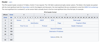
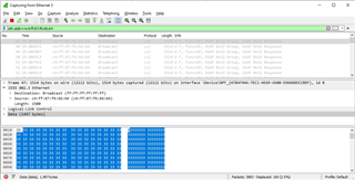
Dev board_1 - Tx side: SRC and DEST address are set to 0xFF. 128 byte of data is initialized to 0xAA.
Dev board _2 - Rx side: Data bytes (0xAA) copied to software buffer. But the RXALIGNCODEERROR count is 1 and the RXGOODFRAMES is 0 and RXBCASTFRAMES is 0. Also, the source address last byte is 0x3F instead of 0xFF.
Issue 2:
Dev board_1 - Tx side: DEST address is set to 0xFF(Broadcast) and SRC address is set to {0x11, 0x22, 0x33, 0x44, 0x55, 0x66}. 128 byte of data is initialized to 0xAA.
Dev board _2 - Rx side: No packet is received and the RXALIGNCODEERROR count is 0, RXGOODFRAMES is 0 and RXBCASTFRAMES is 0.
Note: I checked if the Ethernet cable is faulty by connecting it from my PC to LAN. It is working fine.
Issue 3:
I couldn't see register contents of following registers even when debugger is HALTED. I am seeing the message "Error: Unable to read"
Starting from
500h MACADDRLO MAC Address Low Bytes Register
....
....
67Ch RX7CP Receive Channel 7 Completion Pointer Register
Could you please help to resolve this issue.
Thanks,
Jai