This thread has been locked.

If you have a related question, please click the "Ask a related question" button in the top right corner. The newly created question will be automatically linked to this question.

TMS570LC4357-EP: Interfacing with Asynchronous Device

Part Number: TMS570LC4357-EP

Hello,

We are trying access a Async device via EMIF using nCS2 chip select of EMIF.

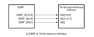
We are configuring EMIF to read 16 bit data.

When the pointer to the address is used using keyword UINT16, BA1 should be LSB of the address. Instead of that BA0 is getting configured as LSB.

Can you please let us know which datatype to be used to  configure exactly for 16bit data.

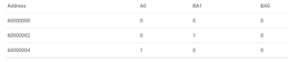
Below is the table of the outputs observed on A0,BA1&BA0 pins of J10 connector on the TMS570LC43x EVM.

Address A0 BA1 BA0
60000000 0 0 0
60000002 0 1 0
60000004 1 0 0

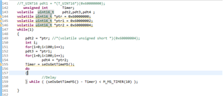
Also, attached snapshot of the code.

  • Hi,

      I found a simulation waveform by our design team that shows the timing matching yours for 0x60000002. The BA[1] will select the upper byte.

    *(unsigned short *)  0x60000102   = 0x2233;

    Below is the description in the TRM. 

    The EMIF address pin EMIF_A[0] always provides the least significant bit of a 32-bit word address. Therefore, when
    interfacing to a 16-bit or 8-bit asynchronous device, the EMIF_BA[1] and EMIF_BA[0] pins provide the
    least-significant bits of the halfword or byte address, respectively.

  • Hello,

    Thanks for the reply.

    BA1 should be LSB of address right and not Byte Select.

    For eg. Address: 0x60000002, A0=1 and BA1=0

  • Hi,

      I suppose you make the below connection to the 16-bit async memory. EMIF_BA[1] is connected to A[0] of a 16-bit memory. As you said, the EMIF_BA[1] is not used as a byte select but rather as an address bit. The first 16-bit memory location is accessed by 0x0 from the memory module perspective. The second memory 16-bit memory location is 0x1 from the memory module perspective. Since the BA[1] is connected to A[0] of the memory module, the BA[1] needs to be high in order to access the 2nd memory location. To access the the 3rd location which is 0x2, the EMIF_A[0] needs to be high and EMIF_BA[1] needs to be low. That is how I interpret it. 

  • Hi,

    Yes. Even our understanding was same as your interpretation.

    Ideally, to access 3rd location 0x02, EMIF_A[0] =1 and EMIF_BA[1] =0 .But we are seeing EMIF_A[0] =0 and EMIF_BA[1] =1. This looks like BA0 is the LSB and not BA1. Can you please clarify on this.

  • HI,

      In your table you showed EMIF_A[0] =1 and EMIF_BA[1] =0 for the third location which is 0x60000004. The 0x60000004 is the CPU address corresponding to 0x2 of the memory module. Basically, it is a right-shift by one bit.