This thread has been locked.

If you have a related question, please click the "Ask a related question" button in the top right corner. The newly created question will be automatically linked to this question.

TM4C123BH6PM: Lost CAN massage object (2)

Part Number: TM4C123BH6PM

Hi Team,

The customer provide the project to re-produce with Tiva DK-TM4C123G.for the following E2E thread, I attached it.

Would you please investigate it?

The original thread is locked. So I create new one.

TM4C123BH6PM: Lost CAN massage object

https://e2e.ti.com/support/microcontrollers/other/f/other-microcontrollers-forum/994417/tm4c123bh6pm-lost-can-massage-obje

TestDK_Bord.zip

< TI.png>

<ti2.png>

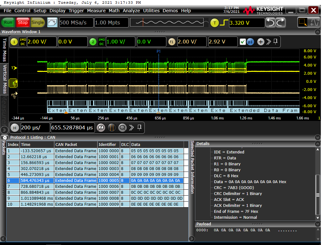
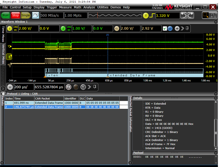
The condition of the can bus when #if is set to 1 on line 186 is indicated in the attachment "TI.png", Can bus status when #if is set to 0 on line 186 is attached "ti2.png"

Thanks and Best regards,

 Kuerbis

  • Hi Akemi,

      I will need some time to investigate this as you know the CAN module as well as the protocol is complicated unlike UART or SPI. If I find something I will reply but most likely not until next week. Please set the expectation straight with your customer. 

  • Hi Akemi,

      I have some updates. 

    I think the reason that you are seeing only the last message on the bus is because the TXRQST bit is immediately cleared by the hardware when you disable the auto-retransmission. When you call CANMessageSet, the software is supposed to set the TXRQST bit and after a successful transmission, and if no new data was
    written to the message object since the start of the transmission, the TXRQST bit in the CANTXRQn register is cleared. However, if the retransmission is disabled, then the TXRQST is somehow cleared before the transmission has completed. When this happens, your check using CANStatusGet will return 0 and it will result in calling CANMessageSet repeatedly for 10 times. In another word, the 10th message will overwrite all the prior 9 messages in the message object before the transmission is started. This is why you are seeing the last message on the bus. 

     I found two workarounds. 

      - First workaround is to wait for the TXOK to interrupt. A TXOK is a status indicating the transmission has completed.

      - Second workaround is to wait for the message object. The message object TX interrupt will work the same way. Message object TX interrupt is only generated after the transmission is complete.

      Attached are two different workarounds. 

    main_use_message_object_interrupt.c
    #include <stdint.h>
    #include <stdbool.h>
    
    #include "inc/hw_memmap.h"
    #include "inc/hw_types.h"
    #include "inc/hw_gpio.h"
    #include "inc/hw_sysctl.h"
    
    #include "inc/hw_can.h"
    #include "inc/hw_ints.h"
    #include "driverlib/interrupt.h"
    
    
    #include "driverlib/gpio.h"
    #include "driverlib/pin_map.h"
    #include "driverlib/rom.h"
    #include "driverlib/sysctl.h"
    
    #include "inc/hw_can.h"
    #include "driverlib/can.h"
    #include "drivers/can_st.h"
    
    //*****************************************************************************
    //
    // CAN message Objects for data being sent / received
    //
    //*****************************************************************************
    tCANMsgObject g_sCAN0RxMessage;
    tCANMsgObject g_sCAN0TxMessage;
    
    //*****************************************************************************
    //
    // Message Identifiers and Objects
    // RXID is set to 0 so all messages are received
    //
    //*****************************************************************************
    #define CAN0RXID                0
    #define RXOBJECT                1
    #define TXOBJECT                30
    
    //*****************************************************************************
    //
    // Variables to hold character being sent / reveived
    //
    //*****************************************************************************
    //uint8_t g_ui8TXMsgData;
    //uint8_t g_ui8RXMsgData;
    uint8_t g_ui8TXMsgData[8];//SSS
    uint8_t g_ui8RXMsgData[8];//SSS
    
    //*****************************************************************************
    //
    // A counter that keeps track of the number of times the TX interrupt has
    // occurred, which should match the number of TX messages that were sent.
    //
    //*****************************************************************************
    volatile uint32_t g_ui32MsgCount = 0;
    
    //*****************************************************************************
    //
    // A flag to indicate that some transmission error occurred.
    //
    //*****************************************************************************
    volatile bool g_bErrFlag = 0;
    volatile bool g_bDoneFlag = 0;
    
    
    //*****************************************************************************
    //
    // This function provides a 1 second delay using a simple polling method.
    //
    //*****************************************************************************
    //*****************************************************************************
    //
    // Setup CAN0 to both send and receive at 500KHz.
    // Interrupts on
    // Use PE4 / PE5
    //
    //*****************************************************************************
    void
    CANIntHandler(void)
    {
        uint32_t ui32Status;
    
        //
        // Read the CAN interrupt status to find the cause of the interrupt
        //
        ui32Status = CANIntStatus(CAN0_BASE, CAN_INT_STS_CAUSE);
    
        //
        // Check if the cause is message object 1, which what we are using for
        // sending messages.
        //
        if(ui32Status == 30)
        {
            //
            // Getting to this point means that the TX interrupt occurred on
            // message object 1, and the message TX is complete.  Clear the
            // message object interrupt.
            //
            CANIntClear(CAN0_BASE, 30);
    
            //
            // Increment a counter to keep track of how many messages have been
            // sent.  In a real application this could be used to set flags to
            // indicate when a message is sent.
            //
            g_ui32MsgCount++;
    
            //
            // Since the message was sent, clear any error flags and set the
            // g_bDoneFlag so that the next message object in the main() can be
            // started.
            //
            g_bDoneFlag = 1;
            g_bErrFlag = 0;
        }
    
        //
        // Otherwise, something unexpected caused the interrupt.  This should
        // never happen.
        //
        else
        {
            //
            // Spurious interrupt handling can go here.
            //
        }
    }
    
    void
    InitCAN0(void)
    {
        tCANBitClkParms CANbitset;
    
        //
        // For this example CAN0 is used with RX and TX pins on port E4 and E5.
        // GPIO port E needs to be enabled so these pins can be used.
        //
        SysCtlPeripheralEnable(SYSCTL_PERIPH_GPIOE);
    
        //
        // Configure the GPIO pin muxing to select CAN0 functions for these pins.
        // This step selects which alternate function is available for these pins.
        //
        GPIOPinConfigure(GPIO_PE4_CAN0RX);
        GPIOPinConfigure(GPIO_PE5_CAN0TX);
    
        //
        // Enable the alternate function on the GPIO pins.  The above step selects
        // which alternate function is available.  This step actually enables the
        // alternate function instead of GPIO for these pins.
        //
        GPIOPinTypeCAN(GPIO_PORTE_BASE, GPIO_PIN_4 | GPIO_PIN_5);
    
        //
        // The GPIO port and pins have been set up for CAN.  The CAN peripheral
        // must be enabled.
        //
        SysCtlPeripheralEnable(SYSCTL_PERIPH_CAN0);
    
        //
        // Initialize the CAN controller
        //
        CANInit(CAN0_BASE);
    
        //
        // Set up the bit rate for the CAN bus.  This function sets up the CAN
        // bus timing for a nominal configuration.  You can achieve more control
        // over the CAN bus timing by using the function CANBitTimingSet() instead
        // of this one, if needed.
        // In this example, the CAN bus is set to 500 kHz.
        //
        //CANBitRateSet(CAN0_BASE, SysCtlClockGet(), 500000);
        CANBitRateSet(CAN0_BASE, SysCtlClockGet(), 125000);
    
    //    CANbitset.ui32Phase2Seg = 2;
    //    CANbitset.ui32SyncPropPhase1Seg = 7;
    //    CANbitset.ui32SJW = 2;
    //    CANbitset.ui32QuantumPrescaler = 5;
    //    CANBitTimingSet(CAN0_BASE, &CANbitset);
        //Sampling Point 80%
    
        //
        // Enable interrupts on the CAN peripheral.  This example uses static
        // allocation of interrupt handlers which means the name of the handler
        // is in the vector table of startup code.
        //
        CANIntEnable(CAN0_BASE, CAN_INT_MASTER | CAN_INT_ERROR );
    //    CANIntEnable(CAN0_BASE, CAN_INT_MASTER | CAN_INT_STATUS);
    
        //
        // Enable the CAN interrupt on the processor (NVIC).
        //
         IntEnable(INT_CAN0);
    
        //
        // Enable the CAN for operation.
        //
        CANEnable(CAN0_BASE);
    
        CANRetrySet(CAN0_BASE, false);
    
        //
        // Initialize a message object to be used for receiving CAN messages with
        // any CAN ID.  In order to receive any CAN ID, the ID and mask must both
        // be set to 0, and the ID filter enabled.
        //
        g_sCAN0RxMessage.ui32MsgID = CAN0RXID;
        g_sCAN0RxMessage.ui32MsgIDMask = 0;
        g_sCAN0RxMessage.ui32Flags = MSG_OBJ_USE_ID_FILTER;
        g_sCAN0RxMessage.ui32MsgLen = sizeof(g_ui8RXMsgData);
        g_sCAN0RxMessage.pui8MsgData = (uint8_t *) g_ui8RXMsgData;
    
        //
        // Now load the message object into the CAN peripheral.  Once loaded the
        // CAN will receive any message on the bus, and an interrupt will occur.
        // Use message object RXOBJECT for receiving messages (this is not the
        //same as the CAN ID which can be any value in this example).
        //
        CANMessageSet(CAN0_BASE, RXOBJECT, &g_sCAN0RxMessage, MSG_OBJ_TYPE_RX);
    
        //
        // Initialize the message object that will be used for sending CAN
        // messages.  The message will be 1 bytes that will contain the character
        // received from the other controller. Initially it will be set to 0.
        //
        //g_ui8TXMsgData = 0;
        g_ui8TXMsgData[0] = 0;
        g_ui8TXMsgData[1] = 0;
        g_ui8TXMsgData[2] = 0;
        g_ui8TXMsgData[3] = 0;
        g_ui8TXMsgData[4] = 0;
        g_ui8TXMsgData[5] = 0;
        g_ui8TXMsgData[6] = 0;
        g_ui8TXMsgData[7] = 0;
    
        g_sCAN0TxMessage.ui32MsgID = 0;
        g_sCAN0TxMessage.ui32MsgLen = sizeof(g_ui8TXMsgData);
        g_sCAN0TxMessage.ui32MsgIDMask = 0;
        g_sCAN0TxMessage.ui32Flags = MSG_OBJ_TX_INT_ENABLE;
    
        g_sCAN0TxMessage.pui8MsgData = (uint8_t *)g_ui8TXMsgData;
    }
    
    void TestCAN(void)
    {
        //ƒXƒe�[ƒ^ƒXŽæ“¾
        uint32_t ui32Status = CANStatusGet(CAN0_BASE, CAN_STS_NEWDAT);
    
        uint32_t count;
        uint32_t status = 0;
    
        for(count=0; count<20; count++){
            g_ui8TXMsgData[0] = count+5;
            g_ui8TXMsgData[1] = count+5;
            g_ui8TXMsgData[2] = count+5;
            g_ui8TXMsgData[3] = count+5;
            g_ui8TXMsgData[4] = count+5;
            g_ui8TXMsgData[5] = count+5;
            g_ui8TXMsgData[6] = count+5;
            g_ui8TXMsgData[7] = count+5;
            g_sCAN0TxMessage.ui32MsgID = 0x10000000 + count;
            g_sCAN0TxMessage.ui32MsgLen = 8;
            CANMessageSet(CAN0_BASE, TXOBJECT, &g_sCAN0TxMessage, MSG_OBJ_TYPE_TX);
    //        SysCtlDelay(SysCtlClockGet() / 833 / 3);
            while (g_bDoneFlag == 0);
            g_bDoneFlag = 0;
    
            // If the retransmission is disabled by CANRetrySet(CAN0_BASE, false) then
            // the TXRQST bit in the CANTXRQ1 register is cleared immediately before the
            // transmission has started. You cannot wait for the TXRQST bit to clear as a condition to start the next
            // start the next transmit because the condition is true all the time. You will be
            // calling the CANMessageSet 10 times before any transmission starts. This is the reason,
            // only the last message is seen on the bus. Therefore, the workaround is to use either TXOK or for
            // the message object to interrupt to indicate the transmission has
            // completed. Note 0x20000000 indicate message object 30 which is used
            // for transmit in this testcase.
    
    
    #if 0
            while(1){
                status = (CANStatusGet(CAN0_BASE, CAN_STS_TXREQUEST) & 0x20000000);
                if(status == 0){
                    break;
                }
                else{
                    status = 0; //test
                }
            }
    #endif
        }
    }
    
    /**
     * main.c
     */
    int main(void)
    {
        //
        // Enable lazy stacking for interrupt handlers.  This allows floating-point
        // instructions to be used within interrupt handlers, but at the expense of
        // extra stack usage.
        //
        ROM_FPULazyStackingEnable();
    
        //
        // Set the clocking to run directly from the crystal.
        //
        ROM_SysCtlClockSet(SYSCTL_SYSDIV_4 | SYSCTL_USE_PLL | SYSCTL_XTAL_16MHZ |
                           SYSCTL_OSC_MAIN);
    
        //
        // Enable the GPIO port that is used for the on-board LED.
        //
        ROM_SysCtlPeripheralEnable(SYSCTL_PERIPH_GPIOG);
    
        //
        // Enable the GPIO pins for the LED (PF2 & PF3).
        //
        ROM_GPIOPinTypeGPIOOutput(GPIO_PORTG_BASE, GPIO_PIN_2);
    
        // test led
        //GPIOPinWrite(GPIO_PORTG_BASE, GPIO_PIN_2, GPIO_PIN_2);
    
        //
        // Initialize CAN0
        //
        InitCAN0();
    
        //
        TestCAN();
    
    	return 0;
    }
    
    main_use_TXOK_status_interrupt.c
    #include <stdint.h>
    #include <stdbool.h>
    
    #include "inc/hw_memmap.h"
    #include "inc/hw_types.h"
    #include "inc/hw_gpio.h"
    #include "inc/hw_sysctl.h"
    
    #include "inc/hw_can.h"
    #include "inc/hw_ints.h"
    #include "driverlib/interrupt.h"
    
    
    #include "driverlib/gpio.h"
    #include "driverlib/pin_map.h"
    #include "driverlib/rom.h"
    #include "driverlib/sysctl.h"
    
    #include "inc/hw_can.h"
    #include "driverlib/can.h"
    #include "drivers/can_st.h"
    
    //*****************************************************************************
    //
    // CAN message Objects for data being sent / received
    //
    //*****************************************************************************
    tCANMsgObject g_sCAN0RxMessage;
    tCANMsgObject g_sCAN0TxMessage;
    
    //*****************************************************************************
    //
    // Message Identifiers and Objects
    // RXID is set to 0 so all messages are received
    //
    //*****************************************************************************
    #define CAN0RXID                0
    #define RXOBJECT                1
    #define TXOBJECT                30
    
    //*****************************************************************************
    //
    // Variables to hold character being sent / reveived
    //
    //*****************************************************************************
    //uint8_t g_ui8TXMsgData;
    //uint8_t g_ui8RXMsgData;
    uint8_t g_ui8TXMsgData[8];//SSS
    uint8_t g_ui8RXMsgData[8];//SSS
    
    //*****************************************************************************
    //
    // A counter that keeps track of the number of times the TX interrupt has
    // occurred, which should match the number of TX messages that were sent.
    //
    //*****************************************************************************
    volatile uint32_t g_ui32MsgCount = 0;
    
    //*****************************************************************************
    //
    // A flag to indicate that some transmission error occurred.
    //
    //*****************************************************************************
    volatile bool g_bErrFlag = 0;
    volatile bool g_bDoneFlag = 0;
    
    
    //*****************************************************************************
    //
    // This function provides a 1 second delay using a simple polling method.
    //
    //*****************************************************************************
    //*****************************************************************************
    //
    // Setup CAN0 to both send and receive at 500KHz.
    // Interrupts on
    // Use PE4 / PE5
    //
    //*****************************************************************************
    void
    CANIntHandler(void)
    {
        uint32_t ui32Status;
    
        //
        // Read the CAN interrupt status to find the cause of the interrupt
        //
        ui32Status = CANIntStatus(CAN0_BASE, CAN_INT_STS_CAUSE);
    
        //
        // If the cause is a controller status interrupt, then get the status
        //
        if(ui32Status == CAN_INT_INTID_STATUS)
        {
            //
            // Read the controller status.  This will return a field of status
            // error bits that can indicate various errors.  Error processing
            // is not done in this example for simplicity.  Refer to the
            // API documentation for details about the error status bits.
            // The act of reading this status will clear the interrupt.  If the
            // CAN peripheral is not connected to a CAN bus with other CAN devices
            // present, then errors will occur and will be indicated in the
            // controller status.
            //
            ui32Status = CANStatusGet(CAN0_BASE, CAN_STS_CONTROL);
    
            //
            // Set a flag to indicate some errors may have occurred or
            // the transmit has completed.
            //
            if ((ui32Status & CAN_STATUS_TXOK) == CAN_STATUS_TXOK)
            {
                g_bDoneFlag = 1;
    
            }
            else
            {
    			g_bErrFlag = 1;
    
            }
        }
    
        //
        // Otherwise, something unexpected caused the interrupt.  This should
        // never happen.
        //
        else
        {
            //
            // Spurious interrupt handling can go here.
            //
        }
    }
    
    void
    InitCAN0(void)
    {
        tCANBitClkParms CANbitset;
    
        //
        // For this example CAN0 is used with RX and TX pins on port E4 and E5.
        // GPIO port E needs to be enabled so these pins can be used.
        //
        SysCtlPeripheralEnable(SYSCTL_PERIPH_GPIOE);
    
        //
        // Configure the GPIO pin muxing to select CAN0 functions for these pins.
        // This step selects which alternate function is available for these pins.
        //
        GPIOPinConfigure(GPIO_PE4_CAN0RX);
        GPIOPinConfigure(GPIO_PE5_CAN0TX);
    
        //
        // Enable the alternate function on the GPIO pins.  The above step selects
        // which alternate function is available.  This step actually enables the
        // alternate function instead of GPIO for these pins.
        //
        GPIOPinTypeCAN(GPIO_PORTE_BASE, GPIO_PIN_4 | GPIO_PIN_5);
    
        //
        // The GPIO port and pins have been set up for CAN.  The CAN peripheral
        // must be enabled.
        //
        SysCtlPeripheralEnable(SYSCTL_PERIPH_CAN0);
    
        //
        // Initialize the CAN controller
        //
        CANInit(CAN0_BASE);
    
        //
        // Set up the bit rate for the CAN bus.  This function sets up the CAN
        // bus timing for a nominal configuration.  You can achieve more control
        // over the CAN bus timing by using the function CANBitTimingSet() instead
        // of this one, if needed.
        // In this example, the CAN bus is set to 500 kHz.
        //
        //CANBitRateSet(CAN0_BASE, SysCtlClockGet(), 500000);
        CANBitRateSet(CAN0_BASE, SysCtlClockGet(), 125000);
    
    //    CANbitset.ui32Phase2Seg = 2;
    //    CANbitset.ui32SyncPropPhase1Seg = 7;
    //    CANbitset.ui32SJW = 2;
    //    CANbitset.ui32QuantumPrescaler = 5;
    //    CANBitTimingSet(CAN0_BASE, &CANbitset);
        //Sampling Point 80%
    
        //
        // Enable interrupts on the CAN peripheral.  This example uses static
        // allocation of interrupt handlers which means the name of the handler
        // is in the vector table of startup code.
        //
        CANIntEnable(CAN0_BASE, CAN_INT_MASTER | CAN_INT_ERROR | CAN_INT_STATUS);
    //    CANIntEnable(CAN0_BASE, CAN_INT_MASTER | CAN_INT_STATUS);
    
        //
        // Enable the CAN interrupt on the processor (NVIC).
        //
         IntEnable(INT_CAN0);
    
        //
        // Enable the CAN for operation.
        //
        CANEnable(CAN0_BASE);
    
        CANRetrySet(CAN0_BASE, false);
    
        //
        // Initialize a message object to be used for receiving CAN messages with
        // any CAN ID.  In order to receive any CAN ID, the ID and mask must both
        // be set to 0, and the ID filter enabled.
        //
        g_sCAN0RxMessage.ui32MsgID = CAN0RXID;
        g_sCAN0RxMessage.ui32MsgIDMask = 0;
        g_sCAN0RxMessage.ui32Flags = MSG_OBJ_USE_ID_FILTER;
        g_sCAN0RxMessage.ui32MsgLen = sizeof(g_ui8RXMsgData);
        g_sCAN0RxMessage.pui8MsgData = (uint8_t *) g_ui8RXMsgData;
    
        //
        // Now load the message object into the CAN peripheral.  Once loaded the
        // CAN will receive any message on the bus, and an interrupt will occur.
        // Use message object RXOBJECT for receiving messages (this is not the
        //same as the CAN ID which can be any value in this example).
        //
        CANMessageSet(CAN0_BASE, RXOBJECT, &g_sCAN0RxMessage, MSG_OBJ_TYPE_RX);
    
        //
        // Initialize the message object that will be used for sending CAN
        // messages.  The message will be 1 bytes that will contain the character
        // received from the other controller. Initially it will be set to 0.
        //
        //g_ui8TXMsgData = 0;
        g_ui8TXMsgData[0] = 0;
        g_ui8TXMsgData[1] = 0;
        g_ui8TXMsgData[2] = 0;
        g_ui8TXMsgData[3] = 0;
        g_ui8TXMsgData[4] = 0;
        g_ui8TXMsgData[5] = 0;
        g_ui8TXMsgData[6] = 0;
        g_ui8TXMsgData[7] = 0;
    
        g_sCAN0TxMessage.ui32MsgID = 0;
        g_sCAN0TxMessage.ui32MsgLen = sizeof(g_ui8TXMsgData);
        g_sCAN0TxMessage.ui32MsgIDMask = 0;
    //    g_sCAN0TxMessage.ui32Flags = MSG_OBJ_TX_INT_ENABLE;
    
        g_sCAN0TxMessage.pui8MsgData = (uint8_t *)g_ui8TXMsgData;
    }
    
    void TestCAN(void)
    {
        //ƒXƒe�[ƒ^ƒXŽæ“¾
        uint32_t ui32Status = CANStatusGet(CAN0_BASE, CAN_STS_NEWDAT);
    
        uint32_t count;
        uint32_t status = 0;
    
        for(count=0; count<20; count++){
            g_ui8TXMsgData[0] = count+5;
            g_ui8TXMsgData[1] = count+5;
            g_ui8TXMsgData[2] = count+5;
            g_ui8TXMsgData[3] = count+5;
            g_ui8TXMsgData[4] = count+5;
            g_ui8TXMsgData[5] = count+5;
            g_ui8TXMsgData[6] = count+5;
            g_ui8TXMsgData[7] = count+5;
            g_sCAN0TxMessage.ui32MsgID = 0x10000000 + count;
            g_sCAN0TxMessage.ui32MsgLen = 8;
            CANMessageSet(CAN0_BASE, TXOBJECT, &g_sCAN0TxMessage, MSG_OBJ_TYPE_TX);
    //        SysCtlDelay(SysCtlClockGet() / 833 / 3);
            while (g_bDoneFlag == 0);
            g_bDoneFlag = 0;
    
            // If the retransmission is disabled by CANRetrySet(CAN0_BASE, false) then
            // the TXRQST bit in the CANTXRQ1 register is cleared immediately before the
            // transmission has started. You cannot wait for the TXRQST bit to clear as a condition to start the next
            // start the next transmit because the condition is true all the time. You will be
            // calling the CANMessageSet 10 times before any transmission starts. This is the reason,
            // only the last message is seen on the bus. Therefore, the workaround is to use either TXOK or for
            // the message object to interrupt to indicate the transmission has
            // completed. Note 0x20000000 indicate message object 30 which is used
            // for transmit in this testcase.
    
    #if 0
            while(1){
                status = (CANStatusGet(CAN0_BASE, CAN_STS_TXREQUEST) & 0x20000000);
                if(status == 0){
                    break;
                }
                else{
                    status = 0; //test
                }
            }
    #endif
        }
    }
    
    /**
     * main.c
     */
    int main(void)
    {
        //
        // Enable lazy stacking for interrupt handlers.  This allows floating-point
        // instructions to be used within interrupt handlers, but at the expense of
        // extra stack usage.
        //
        ROM_FPULazyStackingEnable();
    
        //
        // Set the clocking to run directly from the crystal.
        //
        ROM_SysCtlClockSet(SYSCTL_SYSDIV_4 | SYSCTL_USE_PLL | SYSCTL_XTAL_16MHZ |
                           SYSCTL_OSC_MAIN);
    
        //
        // Enable the GPIO port that is used for the on-board LED.
        //
        ROM_SysCtlPeripheralEnable(SYSCTL_PERIPH_GPIOG);
    
        //
        // Enable the GPIO pins for the LED (PF2 & PF3).
        //
        ROM_GPIOPinTypeGPIOOutput(GPIO_PORTG_BASE, GPIO_PIN_2);
    
        // test led
        //GPIOPinWrite(GPIO_PORTG_BASE, GPIO_PIN_2, GPIO_PIN_2);
    
        //
        // Initialize CAN0
        //
        InitCAN0();
    
        //
        TestCAN();
    
    	return 0;
    }
    

  • Hi Charles,


    Thank you for investigating and finding the workarounds.

    I already inform those to the customer and waiting their feedback.

    If they have any questions and problem, please support them.


    Thanks and Best regards,

    Kuerbis

  • I am the customer to ask this problem.
    Thank you for your advice about the reason and the workarround.
    I understood these.

    But, if possible,
    I want to use TXREQ bit check, becouse I do not want to use some interrupt.

    Now, I can not use sending theree TX objects at a time with Auto-retry disabled, using TXREQ bit check .
    But, I can use sending only one object at a time with Auto-retry disabled, using TXREQ bit check.
    (Using project : main.c Line186 #if is set to 1)

    If the product specifications of TM4C123BH6PM is no problem using my project, I want to use TXREQ bit check.

    Please comment.
    Thanks and Best regards,

  • Hi Yuzo-san,

    But, I can use sending only one object at a time with Auto-retry disabled, using TXREQ bit check.
    (Using project : main.c Line186 #if is set to 1)

    If the product specifications of TM4C123BH6PM is no problem using my project, I want to use TXREQ bit check.

    As I explained in my previous reply, the CANStatusGet() will immediately return 0 if you disable auto-retransmission. Therefore, calling CANStatusGet() is not a reliable way to determine if the CAN message object has been sent out successfully or not. I recommend you consider my proposed workarounds. Did you try them? Please try them to see if they work for you.  

  • Thanks for kind comment.
    Your explanation was very thorough.
    I try to fix my project using your proposed workaround.