This thread has been locked.

If you have a related question, please click the "Ask a related question" button in the top right corner. The newly created question will be automatically linked to this question.

TM4C129ENCPDT: Ethernet LED always ON

Part Number: TM4C129ENCPDT

Hi

We are using TM4C129ENCPDT microcontroller. And it has ethernet communication which is based on the lwip protocol. We have used PK5, PK4 (pin 62,63) for the Ethernet LEDs.

In the PinoutSet() function we have made the following changes  i.e, removed PF0,PF4 initialization and replaced them with PK4,PK5.

//
// this app wants to configure for ethernet LED function
//
// ROM_GPIOPinConfigure(GPIO_PF0_EN0LED0);
// ROM_GPIOPinConfigure(GPIO_PF4_EN0LED1);
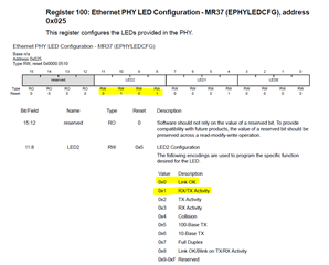
ROM_GPIOPinConfigure(GPIO_PK4_EN0LED0);
ROM_GPIOPinConfigure(GPIO_PK5_EN0LED2);

GPIOPinTypeEthernetLED(GPIO_PORTK_BASE, GPIO_PIN_4 | GPIO_PIN_5);
// GPIOPinTypeEthernetLED(GPIO_PORTF_BASE, GPIO_PIN_0 | GPIO_PIN_4);

Now whenever Ethernet connection is established, both LEDs keeps on glowing continuously. There is no blink during Transmission and Reception.

How to configure the LEDs to blink during transmission and reception.

Thank You for your time.

  • Hi,

      The example is blinking PF0 (Link OK status) and PF4 (RX/TX activity). The PK5 is by default showing (100-Base TX). 

      The link OK status is going to be on all the time once the link is established. PK5 will be on all the time because it is by default showing you are in 100-Base TX. If you want to show different activities, you can program each LED for different function and also the blink rate.  There is the below description. 

    20.4.2.4 LED Interface
    The PHY supports three configurable Light Emitting Diode (LED) pins to indicate link status of a
    port. The Ethernet PHY LED Configuration - MR37 (EPHYLEDCFG) register, address 0x025 can
    be used to assign different functions to each LED. Each LED can be configured to be active during
    one of these events:
    ■ Link OK (0x0)
    ■ RX/TX Activity (0x1)
    ■ TX Activity (0x2)
    ■ RX Activity (0x3)
    ■ Collision (0x4)
    ■ 100-BASE TX speed (0x5)
    ■ 10-Base TX speed (0x6)
    ■ Full Duplex (0x7)
    ■ Link OK/Blink on TX/RX Activity (0x8)

    At reset, LED0 is initialized to display Link OK and LED1 and LED 2 are initialized to the RX/TX
    activity encoding. The blink rate of the LEDs can be set by programming the BLINKRATE bit field
    of the Ethernet PHY LED Control - MR24 (EPHYLEDCR) register, address 0x018

    For example, if you want to set LED2 to "RX/TX" activity and LED0 to "Link OK" status you will do.

    EMACPHYExtendedWrite(EMAC0_BASE, 0, 0x025, 0x100);