Part Number: TM4C123GH6PM
Hi,
I am Facing a Issue with UART
I have verified with Tiva Ware loop back example, its fine and working
But i wish to learn on why my code is not working
Below is my Flow
1. Start with PLL Initialization
void PLL_Init(void){
// 0) configure the system to use RCC2 for advanced features
// such as 400 MHz PLL and non-integer System Clock Divisor
SYSCTL_RCC2_R |= SYSCTL_RCC2_USERCC2;
// 1) bypass PLL while initializing
SYSCTL_RCC2_R |= SYSCTL_RCC2_BYPASS2;
// 2) select the crystal value and oscillator source
SYSCTL_RCC_R &= ~SYSCTL_RCC_XTAL_M; // clear XTAL field
SYSCTL_RCC_R += SYSCTL_RCC_XTAL_16MHZ;// configure for 16 MHz crystal
SYSCTL_RCC2_R &= ~SYSCTL_RCC2_OSCSRC2_M;// clear oscillator source field
SYSCTL_RCC2_R += SYSCTL_RCC2_OSCSRC2_MO;// configure for main oscillator source
// 3) activate PLL by clearing PWRDN
SYSCTL_RCC2_R &= ~SYSCTL_RCC2_PWRDN2;
// 4) set the desired system divider and the system divider least significant bit
SYSCTL_RCC2_R |= SYSCTL_RCC2_DIV400; // use 400 MHz PLL
SYSCTL_RCC2_R = (SYSCTL_RCC2_R&~0x1FC00000) // clear system clock divider field
+ (SYSDIV2<<22); // configure for 80 MHz clock
// 5) wait for the PLL to lock by polling PLLLRIS
while((SYSCTL_RIS_R&SYSCTL_RIS_PLLLRIS)==0){};
// 6) enable use of PLL by clearing BYPASS
SYSCTL_RCC2_R &= ~SYSCTL_RCC2_BYPASS2;
}
2. Initialization of All my UART under usage
void UART013567_Init(void){
SYSCTL_RCGCUART_R |= 0xEB; // Enable Peripheral Clock for UART0,1,3,5,6,7
SYSCTL_RCGCGPIO_R |= 0x1D; // activate port A,C,D,E in which above UART ports are part of.
/*UART0 Port Settings*/
UART0_CTL_R &= ~UART_CTL_UARTEN; // disable UART
UART0_IBRD_R = 8; // IBRD = int(16,000,000 / (16 * 115,200)) = int(8.680)
UART0_FBRD_R = 44; // FBRD = round(0.5104 * 64 ) = 33
// 8 bit word length (no parity bits, one stop bit, FIFOs)
UART0_LCRH_R = (UART_LCRH_WLEN_8|UART_LCRH_FEN);
UART0_CTL_R |= UART_CTL_UARTEN; // enable UART
/*UART1 Port Settings*/
UART1_CTL_R &= ~UART_CTL_UARTEN; // disable UART
UART1_IBRD_R = 8; // IBRD = int(16,000,000 / (16 * 115,200)) = int(8.680)
UART1_FBRD_R = 44; // FBRD = round(0.5104 * 64 ) = 33
// 8 bit word length (no parity bits, one stop bit, FIFOs)
UART1_LCRH_R = (UART_LCRH_WLEN_8|UART_LCRH_FEN);
UART1_CTL_R |= UART_CTL_UARTEN; // enable UART
/*UART3 Port Settings*/
UART3_CTL_R &= ~UART_CTL_UARTEN; // disable UART
UART3_IBRD_R = 8; // IBRD = int(16,000,000 / (16 * 115,200)) = int(8.680)
UART3_FBRD_R = 44; // FBRD = round(0.5104 * 64 ) = 33
// 8 bit word length (no parity bits, one stop bit, FIFOs)
UART3_LCRH_R = (UART_LCRH_WLEN_8|UART_LCRH_FEN);
UART3_CTL_R |= UART_CTL_UARTEN; // enable UART
/*UART5 Port Settings*/
UART5_CTL_R &= ~UART_CTL_UARTEN; // disable UART
UART5_IBRD_R = 8; // IBRD = int(16,000,000 / (16 * 115,200)) = int(8.680)
UART5_FBRD_R = 44; // FBRD = round(0.5104 * 64 ) = 33
// 8 bit word length (no parity bits, one stop bit, FIFOs)
UART5_LCRH_R = (UART_LCRH_WLEN_8|UART_LCRH_FEN);
UART5_CTL_R |= UART_CTL_UARTEN; // enable UART
/*UART6 Port Settings*/
UART6_CTL_R &= ~UART_CTL_UARTEN; // disable UART
UART6_IBRD_R = 8; // IBRD = int(16,000,000 / (16 * 115,200)) = int(8.680)
UART6_FBRD_R = 44; // FBRD = round(0.5104 * 64 ) = 33
// 8 bit word length (no parity bits, one stop bit, FIFOs)
UART6_LCRH_R = (UART_LCRH_WLEN_8|UART_LCRH_FEN);
UART6_CTL_R |= UART_CTL_UARTEN; // enable UART
/*UART7 Port Settings*/
UART7_CTL_R &= ~UART_CTL_UARTEN; // disable UART
UART7_IBRD_R = 8; // IBRD = int(16,000,000 / (16 * 115,200)) = int(8.680)
UART7_FBRD_R = 44; // FBRD = round(0.5104 * 64 ) = 33
// 8 bit word length (no parity bits, one stop bit, FIFOs)
UART7_LCRH_R = (UART_LCRH_WLEN_8|UART_LCRH_FEN);
UART7_CTL_R |= UART_CTL_UARTEN; // enable UART
/*Port A Configuration */
GPIO_PORTA_AFSEL_R |= 0x03; // enable alt funct on PA[1:0]
GPIO_PORTA_DEN_R |= 0x03; // enable digital I/O on PA[1:0]
// configure PA[1:0] as UART
GPIO_PORTA_PCTL_R = (GPIO_PORTA_PCTL_R&0xFFFFFF00)+0x00000011;
GPIO_PORTA_AMSEL_R &= ~0x03; // disable analog functionality on PA
/*Port C Configuration */
GPIO_PORTC_AFSEL_R |= 0xF0; // enable alt funct on PC[7:4]
GPIO_PORTC_DEN_R |= 0xF0; // enable digital I/O on PC[7:4]
// configure PC[7:4] as UART
GPIO_PORTC_PCTL_R = (GPIO_PORTC_PCTL_R&0x0000FFFF)+0x11220000;
GPIO_PORTC_AMSEL_R &= ~0xF0; // disable analog functionality on PC
/*Port D Configuration */
GPIO_PORTD_AFSEL_R |= 0x30; // enable alt funct on PD[5:4]
GPIO_PORTD_DEN_R |= 0x30; // enable digital I/O on PD[5:4]
// configure PD[5:4] as UART
GPIO_PORTD_PCTL_R = (GPIO_PORTD_PCTL_R&0xFF00FFFF)+0x00110000;
GPIO_PORTD_AMSEL_R &= ~0x30; // disable analog functionality on PD
/*Port E Configuration */
GPIO_PORTE_AFSEL_R |= 0x33; // enable alt funct on PE[5:4][1:0]
GPIO_PORTE_DEN_R |= 0x33; // enable digital I/O on PE[5:4][1:0]
// configure PE[5:4][1:0] as UART
GPIO_PORTE_PCTL_R = (GPIO_PORTE_PCTL_R&0xFF00FF00)+0x00110011;
GPIO_PORTE_AMSEL_R &= ~0x33; // disable analog functionality on PE
}
3. Calls of PutChar and Get Char
void print_dmsg(char *dmsg){
int i;
for(i=0;i<strlen(dmsg);i++)
uint8_putc(dmsg[i],DEBUG1);
}
uint8_t uint8_getc(int port_num){
uint8_t data = -1;
switch(port_num)
{
case ENCODER : while((UART7_FR_R&UART_FR_RXFE) != 0);
data = ((uint8_t)(UART7_DR_R&0xFF));
break;
case ZOOM : while((UART3_FR_R&UART_FR_RXFE) != 0);
data = ((uint8_t)(UART3_DR_R&0xFF));
break;
case PT : while((UART1_FR_R&UART_FR_RXFE) != 0);
data = ((uint8_t)(UART1_DR_R&0xFF));
break;
case DEBUG1 : while((UART6_FR_R&UART_FR_RXFE) != 0);
data = ((uint8_t)(UART6_DR_R&0xFF));
break;
case DEBUG2 : while((UART5_FR_R&UART_FR_RXFE) != 0);
data = ((uint8_t)(UART5_DR_R&0xFF));
break;
case CORE : while((UART0_FR_R&UART_FR_RXFE) != 0);
data = ((uint8_t)(UART0_DR_R&0xFF));
break;
default :
print_dmsg("UnConfigured Port Number:");
break;
}
return data;
}
void uint8_putc(uint8_t in_char,int port_num){
uint8_t data = in_char;
switch(port_num)
{
case ENCODER : while((UART7_FR_R&UART_FR_TXFF) != 0);
UART7_DR_R = data;
break;
case ZOOM : while((UART3_FR_R&UART_FR_TXFF) != 0);
UART3_DR_R = data;
break;
case PT : while((UART1_FR_R&UART_FR_TXFF) != 0);
UART1_DR_R = data;
break;
case DEBUG1 : while((UART6_FR_R&UART_FR_TXFF) != 0);
UART6_DR_R = data;
break;
case DEBUG2 : while((UART5_FR_R&UART_FR_TXFF) != 0);
UART5_DR_R = data;
break;
case CORE : while((UART0_FR_R&UART_FR_TXFF) != 0);
UART0_DR_R = data;
break;
default :
print_dmsg("UnConfigured Port Number:");
break;
}
}
4. Final Test
/*Test Debug Port before going forward*/
uint8_putc('A',DEBUG1);
temp_char = uint8_getc(DEBUG1);
if (temp_char != 'A')
while(1);
/*DEBUG1 by default assigned for Debug Message Window*/
print_dmsg("CT_CARD_DIAG\n");
I am not going forward here because my Physical Loop back test fails, physical connection is perfect, already tested with Tivaware loopback, where exactly i am doing wrong ?
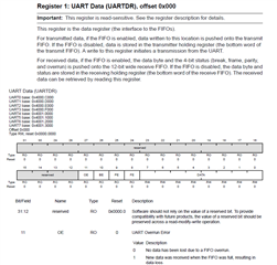
I was able to write to the register map of UART6 while configuration, but if i see whether the data register of UART is actually written, surprisingly there is nothing written there, same is the case of all uart data registers,
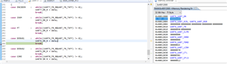
Which means the data written is not actually written to UART_DR