This thread has been locked.

If you have a related question, please click the "Ask a related question" button in the top right corner. The newly created question will be automatically linked to this question.

TM4C123GE6PM: ADC_Conversion

Part Number: TM4C123GE6PM

Hi team,

I have a question for the customer.

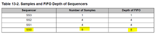
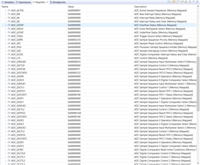
I have a problem with adc device TM4C123 I DESIGN DRIVE TO WORK BU POLLING TO CONTROL THE LED SWITCH ON /OFF BY THE VALUE of FIFO REGISTER, although I flow the instruction section in the datasheet the code did not work properly and the led did not turn off in the if condition becomes true. I try to debug the code and I found that everything works fine so I pass this code to e2e team to discover this problem.

ADC_POLLING_T1.rar

Thank you very much for your help.

Best regards,

  • HI Zhonghui,

      What value did you get when you read the ADC? In your code, you will turn off LED if the value is less than 2048. 

      Can you do some experiments?

      - If you tie the ADC input to ground, what value will you get?

      - I suppose you have your own custom board. Is that correct? Can you run your code on the LaunchPad? Does it work? I want to know if you have a board problem. 

      - Since you develop your own drivers for the entire device, it is very difficult for me to support. Is there any reason that you do not want to use TivaWare? For experiment, can you use the TivaWare ADC example to take sample on Port E3 and what do you measure on your custom board?

      -Last thing is if you can successfully sample and measure the input on PE3 pin using TivaWare example then save the register settings and compare with your own driver code. When you compare the register settings between them you should have an idea on what is different that may cause your driver to not work. 

  • Hi Tsai,

    Thank you for your help.I ask questions for customers:

    I fix this problem by enable interrupt bit in the ADCSSCTL even without using the interrupt but know i try to use 3 channel and every channel read by polling the value of variable resister so how can i read my 8 channel in the same time with my only 4 FIFO registers.

    This code works fine with tiva c if I use only one channel but did not work with 2 or more.

    Thanks.

    Best regards,

  • Hi,

    how can i read my 8 channel in the same time with my only 4 FIFO registers.

    Per your code, you are using SS0 which has the FIFO that can hold 8 entries, not 4. 

        ADCSequenceStepConfigure(ADC0_BASE, 0, 0, ADC_CTL_CH0 ); // Channel 0 is the step 0 of SS0. 
        ADCSequenceStepConfigure(ADC0_BASE, 0, 1, ADC_CTL_CH1 ); // Channel 1 is the step 1 of SS0. 
        ADCSequenceStepConfigure(ADC0_BASE, 0, 2, ADC_CTL_CH2 ); // Channel 2 is the step 2 of SS0. 
        ADCSequenceStepConfigure(ADC0_BASE, 0, 3, ADC_CTL_CH3 ); // Channel 3 is the step 3 of SS0. 
        ADCSequenceStepConfigure(ADC0_BASE, 0, 4, ADC_CTL_CH4 ); // Channel 4 is the step 4 of SS0. 
        ADCSequenceStepConfigure(ADC0_BASE, 0, 5, ADC_CTL_CH5 ); // Channel 5 is the step 5 of SS0. 
        ADCSequenceStepConfigure(ADC0_BASE, 0, 6, ADC_CTL_CH6 ); // Channel 6 is the step 6 of SS0. 
        ADCSequenceStepConfigure(ADC0_BASE, 0, 7, ADC_CTL_CH7 | ADC_CTL_IE |
                                 ADC_CTL_END) // Channel 7 is the step 7 in SS0. Step 7 is the last channel in SS0. Generate interrupt
                                              // when channel 7 is sampled. 
        
       
        ADCSequenceStepConfigure(ADC0_BASE, 1, 0, ADC_CTL_CH8 | ADC_CTL_IE |
                                  ADC_CTL_END); // Assign channel 8 to SS1 as step 0. Step 0 is the last channel in SS1
                                                // Generate interrupt when channel 8 in SS1 is sampled. 

    Please see above example code to setup 8 channels in SS0 and 1 channel in SS1. You need to make sure the last channel in the group is enabled for interrupt and it is declared as the last channel using ADC_CTL_END. I strongly recommend the customer to look at TivaWare sample example. 

  • Hi Tsai,

    Thank you for your help.
    The customer asked that could you help on my code because tivaware has a lot of layer which it to default to trace and debug.

    Thanks.


    Best regards,

  • Hi,

      I think TivaWare is extremely simple to understand even if the customer doesn't want to use it. Your customer creates custom drivers for himself. It is to me very difficult to follow as I'm not the developer for it. Again, please ask the customer to do below.

      1. Tie the ADC input PE3 to ground, what value will you get  using "TivaWare" driver? We need to make sure there is no hardware problem.

      2. Save the ADC register settings in CCS register window for running the TivaWare driver.

      3. Tie the ADC input PE3 to ground, what value will you get  using your "custom" driver?

      4. Save the ADC register settings  in CCS register window for running your custom driver.

      5. Please show the register settings in step both 2 and 4 so we can compare what was the problem. 

  • Hi Tsai,

    Thank you for your time.
    I send a feedback for the customer.

    "I edit some code in the adc drive for multi channel but did not work . i configured my second channel control register to be the end and enable the interrupt but it did not work . i need direct way to communicate with them directly via Facebook or any social media . note check my last version. 

    I just want to E2E to check my code its designed simple code. But i configer the last channel channel 2 control register to have intrupt and enable end BITS and both in mux 0 is there any whatapp groups or any thing else to communication with them.
    My QUESTIONs will be dsisive and short"

    ADC_POLLING_MULTI_CHANNEL.rarADC_POLLING_MULTI_CHANNEL (1).rar

    Thanks.


    Best regards,

  • Hi,

      It looks like the customer never takes my advice on how to debug his code. Here is a complete TivaWare code that will sample two channels. I also capture the entire register settings. In this example, I tie AIN0 to 3.3V and AIN1 to ground when running the example. Why don't you ask the customer to compare his register settings running his code against my example. I configure AIN0 and AIN1 to be used in SS0 for sampling. I think this is the best way to debug his code. 

    #include <stdbool.h>
    #include <stdint.h>
    #include "inc/hw_memmap.h"
    #include "driverlib/adc.h"
    #include "driverlib/gpio.h"
    #include "driverlib/pin_map.h"
    #include "driverlib/sysctl.h"
    #include "inc/hw_types.h"
    #include "driverlib/rom_map.h"
    #include "driverlib/rom.h"
    #include "inc/tm4c123gh6pm.h"
    #include "driverlib/debug.h"
    
    uint32_t ui32ADC0Value[2];
    
    int main(void)
    {
        // Configure for SYSCLK=40Mhz
        SysCtlClockSet ( SYSCTL_SYSDIV_5|SYSCTL_USE_PLL|SYSCTL_OSC_MAIN|SYSCTL_XTAL_16MHZ ) ;
    
        // Enable ADC0
        SysCtlPeripheralEnable(SYSCTL_PERIPH_ADC0);
    
        // Enable GPIO PortE
        SysCtlPeripheralEnable(SYSCTL_PERIPH_GPIOE);
    
        // PE3 for AIN0
        GPIOPinTypeADC(GPIO_PORTE_BASE, GPIO_PIN_3);
    
        // PW2 for AIN1
        GPIOPinTypeADC(GPIO_PORTE_BASE, GPIO_PIN_2);
    
        // Use CPU to trigger the ADC operation on Sequence Number SS0.
        ADCSequenceConfigure(ADC0_BASE, 0, ADC_TRIGGER_PROCESSOR, 0);
    
        // SS0 can support up to 8 steps. For this example, only use two steps.
        // ConfigureStep 0 for AIN0 (ADC_CTL_CH0)
        ADCSequenceStepConfigure(ADC0_BASE, 0, 0, ADC_CTL_CH0 );
    
        // Configure SS0, Step 1 for AIN1 (ADC_CTL_CH1). Enable interrupt for AIN1 and make AIN1 as
        // as the last step.
        ADCSequenceStepConfigure(ADC0_BASE, 0, 1, ADC_CTL_CH1 | ADC_CTL_IE |
                                 ADC_CTL_END);
    
        // Enable SS0
        ADCSequenceEnable(ADC0_BASE, 0);
    
        // Clear any pending interrupt
        ADCIntClear(ADC0_BASE, 0);
    
        while(1)
        {
            // Trigger the ADC conversion
            ADCProcessorTrigger(ADC0_BASE, 0);
    
            // Wait until the sample sequencer SS0 has completed.
            while(!ADCIntStatus(ADC0_BASE, 0, false))
            {
            }
            ADCIntClear(ADC0_BASE, 0);
    
            // Read AIN0 and AIN1 value into buffer.
            ADCSequenceDataGet(ADC0_BASE, 0, ui32ADC0Value);
    
            SysCtlDelay(SysCtlClockGet() / 12);
        }
    }

    i need direct way to communicate with them directly via Facebook or any social media . note check my last version. 
    is there any whatapp groups or any thing else to communication with them.

    I don't understand what the customer is asking about for Facebook or Whatapp app. We can only support MCU questions in this forum. There is no other means to answer questions via Facebook or Whatapp. Perhaps, I'm not understanding the question here.