This thread has been locked.

If you have a related question, please click the "Ask a related question" button in the top right corner. The newly created question will be automatically linked to this question.

TMS570LC4357: Questions on UART_BOOTLAODER

Part Number: TMS570LC4357


Hi all:

   First of all, I met a problem when I debug my uart_bootloader code and the code is totally same as the this link: .

   Here are the questions:

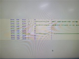
   1. When I use secureCRT to transmit .bin file,  the terminal would show below:

 , which means that the program  gets stuck here;

then I use  serial port monitor and find out the secureCRT sends first packet

  ,   there are no response  such as ACK or NAK but just CRC.

   2. After that I debug my code, then I find that the program enter here and then break out. I think the function  UART_getChar may  occure timeout error? However, how could time out happen? The timeout here is about 3s.


   3. The setting of my SCI port is 115200, 8-bit length, no parity, no flow control, no odd/even and The sci port I use is SCI4 but not SCI1 or SCI2.

   I have stuck here for a week, please help me out, thanks.

Thanks 

Li

  • Li,

    Did you configure the Pinmux for SCI4_RX? Did the uart bootloader work on CI1 or SCI2 of your board?

  • 1.  I have configured the pinmux for SCI4:

    pinMuxReg->PINMUX[32] = PINMUX_BALL_A13_SCI4RX | PINMUX_BALL_J1_N2HET1_18 | PINMUX_BALL_B13_SCI4TX | PINMUX_BALL_P2_N2HET1_20;

     2. I did not try bootloader code on launchpad but just our product. The SCI1 and 2 are not connected to product form MCU in hardware, so I can only test SCI4.

  • The pinmux config is ok.

    It looks like the SCI4 is not able to receive data in your setup. The SCI4 module has a internal loopback feature which connects the transmitter to the receiver internally. would you do a quick test if SCI4 module can receive the data using the loopback mode (either digital loopback or analog looback)?

  • I tried the loopback mode by using code below:

     sciRegBase->GCR1 = (1U << 25U)                      /* enable transmit */
                      | (1U << 24U)                         		/* enable receive */
                      | (1U << 16U) 						/* enable loopback mode*/
                      | (1U << 5U)                          		/* internal clock (device has no clock pin) */
                      | (0U << 4U)       					/* number of stop bits */ 
                      | (0U << 3U)                          		/* even parity, otherwise odd */
                      | (0U << 2U)  						 /* disable parity */
                      | (1U << 1U);                         		/* asynchronous timing mode */
    

    Then I sent a string , after that I used oscilloscope to observe TX and Rx. I found that there are no voltage level change during the transmission. The TX is always high and the same to RX.

    I also tried to set the SCI to normal mode, then I can find voltage level change on TX.

  • If you use the digital loopback, the data will not output to the SCI TX bus. Is the received data same as the TXed data?

  • My code is below:

    void sci4init(void)
    {
      U8 i=0;
      U32 update=0;
      
      tUartSci4_device.channel = (U16)SCI2;
      uartSci4DevInit();
      uartInit(&tUartSci4_device);  
      
      UART_putString(UART, "Hercules MCU UART BootLoader\n ");
      for(i=0;i<30;i++)
      	{
      		packet_data1[i] = UART_getChar(UART, WAIT_TIMEOUT);
      	}
    }

    1.  Our product is based on rtos and sci4init() is first line in main function.

    void main(void) __attribute__ ((naked));
    void main(void)
    {
    
      /* Add by lxy: Init SCI4 for UART_Bootloader*/
      /* The hardware port X3 on producet is connected to SCI4 */
      /***************************/
     sci4init();
      //checkforupdate();
    
      /*rtos init*/
      rtosInit();
      /* general purpose input / output - used by FWU reading the /KEY_UPDATE and driving the /UPDATE signals */
      gioInit();
    
      /* error signaling module */
      esmInit();
    
      hetInit();
      //hetSetOut(Q_HET_IO_PIN_17|Q_HET_IO_PIN_18|Q_HET_IO_PIN_21);
     
      rtosStart();
    
    #if defined(TMS570LCx3)
      // return 0;
    #endif
    }

    2. When the code run normally(without sci4init()), after init then leds of our product will blink.  After adding sci4init(), there is not while loop in this function, so the code should run and then init successfully and led will blink but nothing happened.

    3. This situation looks like something wrong with sci4 loopback mode.

    4. I am sorry I don't have launchboard and can not do debug. When add sci4init(), I can not even connect to upper computer

    5. After testing, I think found that my product will be stuck for about 1 minute which corresponding to the waittime(1.4s)*30. So I think the rx is always time out

  • I just did a loopback test, there is no problem: sciREG4->Rd = sciREG4->Td

    The SCI4 signals are not routed to connectors, so I am not able to test the bootloader on SCI4.

  • So in your test, there is no problem to use SCI4  port as uart_bootlaoder?

  • I didn't see any issue with my loopback (digital and analog) test. I am not able to test bootloader using SCI4 since SCI4 signals are not routed to the connectors on launchpad. 

  • what is the function of sciEnableNotification()? To set the rx interrupt? Is that necessary in uart_bootloader? or just in loopback mode?

  • Hi,

    I just did a test on HDK. The SCI4 works fine.

    My setup is:

    SCI3 RX is connected to SCI4 TX

    SCI3 TX is connected to SCI4 RX

    SCI3 TX data, and the SCI4 gets the same data.

    sciEnableNotification() is used to enable the UART bootloader. The UART bootloader doesn't not require UART bootloader.

  • Finally, I set baudrate to 9600, then SCI4 can receive the data with Ymodem protocl.However, after MCU finishing receiving all data, the MCU will still reply C(CRC) and will  not stop. Then I using serial monitor, I found that secureCRT send the EOT ,then MCU will reply ACK, after that MCU will always reply CRC.

    Here is the code I used:

    int Ymodem_Receive (sciBASE_t *sci, char *buf)
    {
    #if 1
      U8 packet_data[PACKET_1K_SIZE + PACKET_OVERHEAD];
      U8 file_size[FILE_SIZE_LENGTH];
      U8 *file_ptr;
      I8 *buf_ptr;
      I16 i, packet_length, file_done, packets_received;
      I16 session_done=0, errors=0, size = 0;
      I16 retValue;
      U16 oReturnCheck,updateStatusBank;
    
      updateStatusBank = 0;
    
      /* Initialize FlashDestination variable */
      FlashDestination = S1_START_ADDRESS; //bank1 addr 
     
        while( session_done == 0 )
          {
    	   packets_received = 0;
    	   file_done=0;
    	   buf_ptr = buf;
    	   while( file_done == 0 )
    	   {
    	    // memcpy(0, packet_data , 1029);
    	     retValue =  receive_packet(sci, packet_data, &packet_length); //一帧一帧的读出来
    	     switch ( retValue )
    	     {
    	 	case 0:
    	 	errors = 0;
    	 	switch (packet_length)
    	 	{
    	 	  case -1:   /* Abort by sender */
    	 		UART_txByte(UART, ACK);
    	 		return 0;
    	 	  case 0:     /* End of transmission */
    	 		UART_txByte(UART, ACK);
    	 		file_done = 1;	  
    	 		break;
    	 	  default: /* Normal packet */
    	 		if ((packet_data[PACKET_NUM_INDEX] & 0xff) != (packets_received & 0xff)) // 序号出错
    	 		{
    	 		  UART_txByte(UART, NAK);
    	 		}
    	 		else
    	 		{//序号正确
    	 		  if (packets_received == 0) //即第一帧,其中数据帧为0,直到第二帧开始才有真正的数据传过来
    	 		  {
    	 		  	
    	 		     /* Filename packet */
    	 		     if (packet_data[PACKET_HEADER] != 0) //文件名字
    	 		     {
    	
    	 			 /* Filename packet has valid data */
    	 			 for (i = 0, file_ptr = packet_data + PACKET_HEADER; (*file_ptr != 0) && (i < FILE_NAME_LENGTH);)
    	 			 {
    	 			    fileName[i++] = *file_ptr++;
    	 			 }
    	 			 fileName[i++] = '\0'; //文件名最后加结束符
    	 			 for (i = 0, file_ptr ++; (*file_ptr != ' ') && (i < FILE_SIZE_LENGTH);)
    	 			 {
    	 			   file_size[i++] = *file_ptr++;
    	 			 }
    	 			 file_size[i++] = '\0'; //文件大小
    	 			 Str2Int(file_size, &size);
    	 	
    	  			 /* Test the size of the image to be sent */
    	  			 /* Image size is greater than Flash size */
    	  			 /* Erase the FLASH pages */
    	 			 //这里是检测file大小是否超过了flash的大小,这里的flash大小定义必须修改成LC4357的,若判断失败就cancel
      					
    				 if(!Fapi_UartBootloader_checkStartAddr(FlashDestination,  size))
    	 			 {
    	 				UART_txByte(sci, CAN);
    	 				UART_txByte(sci, CAN);
    	 				return -1;
    	 			 }
    	 			 /* Initialize the Flash Wrapper registers */
    	 			 //这里是擦除掉flash
    	 			 oReturnCheck = 0;
    	 			 oReturnCheck = Fapi_UartBootloader_BlockErase( 0, FlashDestination, size);
    	 			
    	 			 // Return an error if an access violation occurred.
    	 			 if(oReturnCheck)
    	 			 {
    	 			   UART_txByte(sci, CAN);
    	 			   UART_txByte(sci, CAN);
    	 			   return -2;
    	 			 }
    		
    	 			 UART_txByte(sci, ACK);
    	 			 UART_txByte(sci, CRC);
    	
    	                    }
    				
    	 		     /* packet_data[PACKET_HEADER] = 0: Filename packet is empty, end session */
    	 		     else
    	 		     {
    	 			 UART_txByte(sci, ACK);
    	 			 file_done = 1;
    	 			 session_done = 1;
    	 			 break;
    	 		      }  //end of "if (packet_data[PACKET_HEADER] != 0), else"
    			
    	 		   }
    		
    
    	 		   /* packets_received != 0: Data packet */ //第二帧开始才有数据帧传过来
    	 		  else
    	 		  {
    	 			memcpy(buf_ptr, packet_data + PACKET_HEADER, packet_length);
    	 			oReturnCheck = Fapi_UartBootloader_BlockProgram( 0, FlashDestination, (unsigned long)buf, packet_length);
    	 			if(oReturnCheck)  //正常等于0
    	 			{
    	 				// Indicate that the flash programming failed.
    	 				UART_txByte(UART, CAN);
    	 				UART_txByte(UART, CAN);
    	 				return -2;
    	 			}
    	 			// Now update the address to program.
    	 			FlashDestination += packet_length;
    	 			UART_txByte(UART, ACK);
    	 		  }// end of "if (packets_received == 0), else"
    	 		  packets_received ++; //第2帧  -> 第N帧
    	 		} /* sequence number ok */
    	 		break;
    	 	    } //end of switch (packet_length)
    	 	    break;
    	 	    case 1:    /*ABORT1 and ABORT2*/
    	 		UART_txByte(UART, CAN);
    	 		UART_txByte(UART, CAN);
    	 	    return -3;      //Aborted by user
    	 	    default:
    	 		 if (packets_received != 0)
    	 		 {
    	 		    errors ++;
    	 		    if (errors > MAX_ERRORS)
    	 		    {
    	 		       UART_txByte(UART, CAN);
    	 		       UART_txByte(UART, CAN);
    	 		       return 0;
    	 		    }
    	 		  }
    	 	        UART_txByte(UART, CRC);
    	 		 break;
    	 	     }//end of switch
    	 	  }//end of 2nd while()
    	 	}//end of 1st while()
     
         return (int)size;   
    
    #endif

    1. I have a question on this function"key = UART_getChar(sci, PACKET_TIMEOUT);"  The para PACKET_TIMEOUT here I set is " 0xF0000", I want to know how to set this time out?

    2. my HCLK is 150MHZ;

             GCLK is 300MHZ;

             VCLK1 75MHZ,

    Is anything wrong with clock setting?

  • Please take a look at the Ymodel protocol. In my example of uart bootloader, I use 1 seconds for the timeout. 

    6.3.2 Receive_Program_Considerations The receiver has a 10-second timeout. It sends a <nak> every time it times out. The receiver's first timeout, which sends a <nak>, signals the transmitter to start. Optionally, the receiver could send a <nak> immediately, in case the sender was ready. This would save the initial 10 second timeout. However, the receiver MUST continue to timeout every 10 seconds in case the sender wasn't ready. Once into a receiving a block, the receiver goes into a one-second timeout for each character and the checksum. If the receiver wishes to <nak> a block for any reason (invalid header, timeout receiving data), it must wait for the line to clear. See "programming tips" for ideas.

    https://techheap.packetizer.com/communication/modems/xmodem-ymodem_reference.html

  • Thanks, I changed the time out to 1s and baudrate to 115200 then it worked. However, When I finished transmitting binary file, the MCU will keep replying CRC, I have tried a lot ways but not worked. The code I used is :

    int Ymodem_Receive (sciBASE_t *sci, char *buf)
    {
    #if 1
      U8 packet_data[PACKET_1K_SIZE + PACKET_OVERHEAD];
      U8 file_size[FILE_SIZE_LENGTH];
      U8 *file_ptr;
      I8 *buf_ptr;
      I16 i, packet_length, file_done, packets_received;
      I16 session_done=0, errors=0, size = 0;
      I16 retValue;
      U16 oReturnCheck;
    
      packets_received= 0;
    
      /* Initialize FlashDestination variable */
      FlashDestination = S1_START_ADDRESS; //bank1 addr 
     
        while( session_done == 0 )
          {
    	   packets_received = 0;
    	   file_done=0;
    	   buf_ptr = buf;
    	   while( file_done == 0 )
    	   {
    	     retValue =  receive_packet(sci, packet_data, &packet_length); //一帧一帧的读出来
    	     switch ( retValue )
    	     {
    	 	case 0:
    	 	errors = 0;
    		
    	 	switch (packet_length)
    	 	{
    	 	  case -1:   /* Abort by sender */
    	 		UART_txByte(UART, ACK);
    	 		return 0;
    	 	  case 0:     /* End of transmission */
    	 		UART_txByte(UART, ACK); 
    			session_done=1; // add here then after receiving first frame , then the loop will done and retrun out,
    	 		file_done =1;	 			
    	 		break;
    	 	  default: /* Normal packet */
    	 		if ((packet_data[PACKET_NUM_INDEX] & 0xff) != (packets_received & 0xff)) // 序号出错
    	 		{
    	 		  UART_txByte(UART, NAK);
    	 		}
    	 		else
    	 		{//序号正确
    	 		  if (packets_received == 0) //即第一帧,其中数据帧为0,直到第二帧开始才有真正的数据传过来
    	 		  {
    	 		     /* Filename packet */
    	 		     if (packet_data[PACKET_HEADER] != 0) //文件名字
    	 		     {
    	
    	 			 /* Filename packet has valid data */
    	 			 for (i = 0, file_ptr = packet_data + PACKET_HEADER; (*file_ptr != 0) && (i < FILE_NAME_LENGTH);)
    	 			 {
    	 			    fileName[i++] = *file_ptr++;
    	 			 }
    	 			 fileName[i++] = '\0'; //文件名最后加结束符
    	 			 for (i = 0, file_ptr ++; (*file_ptr != ' ') && (i < FILE_SIZE_LENGTH);)
    	 			 {
    	 			   file_size[i++] = *file_ptr++;
    	 			 }
    	 			 file_size[i++] = '\0'; //文件大小
    	 			 Str2Int(file_size, &size);
    	 	
    	  			 /* Test the size of the image to be sent */
    	  			 /* Image size is greater than Flash size */
    	  			 /* Erase the FLASH pages */
    	 			 //这里是检测file大小是否超过了flash的大小,这里的flash大小定义必须修改成LC4357的,若判断失败就cancel
      					
    				 if(!Fapi_UartBootloader_checkStartAddr(FlashDestination,  size))
    	 			 {
    	 				UART_txByte(sci, CAN);
    	 				UART_txByte(sci, CAN);
    	 				return -1;
    	 			 }
    	 			 /* Initialize the Flash Wrapper registers */
    	 			 //这里是擦除掉flash
    	 			 oReturnCheck = 0;
    	 			 oReturnCheck = Fapi_UartBootloader_BlockErase( 0, FlashDestination, size);
    	 			
    	 			 // Return an error if an access violation occurred.
    	 			 if(oReturnCheck)
    	 			 {
    	 			   UART_txByte(sci, CAN);
    	 			   UART_txByte(sci, CAN);
    	 			   return -2;
    	 			 }
    		
    	 			 UART_txByte(sci, ACK);
    	 			 UART_txByte(sci, CRC);
    	
    	                    }
    				
    	 		     /* packet_data[PACKET_HEADER] = 0: Filename packet is empty, end session */
    	 		     else 
    	 		     {
    	 			 UART_txByte(sci, ACK);
    	 			 file_done = 1;
    	 			 session_done = 1;
    	 			 break;
    	 		      }  //end of "if (packet_data[PACKET_HEADER] != 0), else"
    			
    	 		   }
    	
    	 		   /* packets_received != 0: Data packet */ //第二帧开始才有数据帧传过来
    	 		  else
    	 		  {
    	 		  	   	
    	 			memcpy(buf_ptr, packet_data + PACKET_HEADER, packet_length);
    	 			oReturnCheck = Fapi_UartBootloader_BlockProgram( 0, FlashDestination, (unsigned long)buf, packet_length);
    	 			if(oReturnCheck)  //正常等于0
    	 			{
    	 				// Indicate that the flash programming failed.
    	 				UART_txByte(UART, CAN);
    	 				UART_txByte(UART, CAN);
    	 				return -2;
    	 			}
    	 			// Now update the address to program.
    	 			FlashDestination += packet_length;
    	 			UART_txByte(UART, ACK);
    				#if 0
    	 		       if(packet_data[3]==0x0 && packet_data[4]==0x30 && packet_data[5]==0x20 && packet_data[6]==0x30 && packet_data[7]==0x20 && packet_data[8]==0x30)
    	 		       {
    	 		         return (int)size;
    	 		      	}
    		             #endif 	
    	 		  }// end of "if (packets_received == 0), else"
    	 		  packets_received ++; //第2帧  -> 第N帧
    	 		} /* sequence number ok */
    	 		break;
    	 	    } //end of switch (packet_length)
    	 	    break;
    	 	    case 1:    /*ABORT1 and ABORT2*/
    	 		UART_txByte(UART, CAN);
    	 		UART_txByte(UART, CAN);
    	 	    return -3;      //Aborted by user
    	 	    default:
    	 		 if (packets_received != 0)
    	 		 {
    	 		    errors ++;
    	 		    if (errors > MAX_ERRORS)
    	 		    {
    	 		       UART_txByte(UART, CAN);
    	 		       UART_txByte(UART, CAN);
    	 		       return 0;
    	 		    }
    	 		  }
    	 	        UART_txByte(UART, CRC);
    	 		 break;
    	 	     }//end of switch
    	 	  }//end of 2nd while()
    	 	}//end of 1st while()
     
         return (int)size;   

    When I use SECURECRT with "send Ymodem", then MCU can receive all data and CRCR right but after that MCU will keep sending CRC instead of return (int)size.

    I  change the code here:

    switch (packet_length)
    	 	{
    	 	  case -1:   /* Abort by sender */
    	 		UART_txByte(UART, ACK);
    	 		return 0;
    	 	  case 0:     /* End of transmission */
    	 		UART_txByte(UART, ACK); 
    			session_done=1; // add here then after receiving first frame , then the loop will done and retrun out,
    	 		file_done =1;	 			
    	 		break;

    I really wonder why that happen?

    By the way, I  read the Ymodem protocl and find that if using SecureCRT with "Send Ymodem", the protcol of "EOT" is like

      SENDER                                  RECEIVER
                                                      "sb foo.*<CR>"
              "sending in batch mode etc."
                                                      C (command:rb)
              SOH 00 FF foo.c NUL[123] CRC CRC
                                                      ACK
                                                      C
              SOH 01 FE Data[128] CRC CRC
                                                      ACK
              STX 02 FD Data[1024] CRC CRC
                                                      ACK
              SOH 03 FC Data[128] CRC CRC
                                                      ACK
              SOH 04 FB Data[100] CPMEOF[28] CRC CRC
                                                      ACK
              EOT
                                                      NAK
              EOT
                                                      ACK
                                                      C
              SOH 00 FF NUL[128] CRC CRC
                                                      ACK

    But if I use "Send Xmodem", the EOT is like:

      SENDER                                  RECEIVER
                                                      "s -k foo.bar"
              "foo.bar open x.x minutes"
                                                      C
              STX 01 FE Data[1024] CRC CRC
                                                      ACK
              STX 02 FD Data[1024] CRC CRC
                                                      ACK
              SOH 03 FC Data[128] CRC CRC
                                                      ACK
              SOH 04 FB Data[100] CPMEOF[28] CRC CRC
                                                      ACK
              EOT
                                                      ACK

    I tried both of them but no one can retrun value.

  • I will check your code this weekend, and come back to you next Monday.

  • thank you!

  • By thw way, Here are three pictures are what I tested with my code:

    1. upper computer finishes sending binary file, and MCU keep replying CRC:

    2. SecureCRT with "Send Xmodem" when at EOT:

    2. SecureCRT with "Send Ymodem" when at EOT:

  • Hi wang, how about testing?  I find something new that the SecureCRT report me that the MCU never response the start of transmission .

     1.I add the uart_putstring() in receiving first frame , but nothing ouput to the secureCRT so I think maybe the transmission may be wrong at the beginning of transmiison.

    2. By the way, I do not add the _copytoram_() function to copy F021 api from Flash to ram, is that matter?

  • This image shows that the code has been transferred. You can check the memory to see if the code is there.

  • If the application start address is in flash bank 1, you don't have to copy the flash APIs to SRAM using _copytoram_()

  • the application start address is in bank0 0x0010_0000. In my product, we have alreadly copy the f021 lib to flash 0 with codes below:

    flashModules.ld:

    *(EXCLUDE_FILE(build/R5_stage0_newIP/flash.o                          
                   build/R5_stage0_newIP/TI_Fapi_UserDefinedFunctions.o   
                   lib/F021_API_CortexR4_BE_L2FMC_V3D16_NDS.lib)                                       
      .text*)                                                         
    

    ram_funcs.ld

    .ram_funcs :                                                      
    {                                                                 
      ram_funcs_start = .;                                            
      build/R5_stage0_newIP/flash.o (.text*)                              
      build/R5_stage0_newIP/TI_Fapi_UserDefinedFunctions.o (.text*)       
      lib/F021_API_CortexR4_BE_L2FMC_V3D16_NDS.lib (.text:*)                                           
    } > RAM_CODE AT > FLASH0                                        
    ram_funcs_size = SIZEOF(.ram_funcs);                              
    ram_funcs_load_start = LOADADDR(.ram_funcs);                      
    

    gcc.ld

    SECTIONS
    {
        .text :
        {
            KEEP(*(.intvecs))
            
            INCLUDE build/flashModules.ld
            *(.LCFG_SECTION)                    
            *(.rodata*)
        } > FLASH0
        
        .ram_allocate :
        {
          ram_allocate_start = .;
        } > RAM_ALLOCATE
        ram_allocate_size = LENGTH(RAM_ALLOCATE); 
    
        INCLUDE build/ram_funcs.ld  
    }

    I think in my ld file, I have already copy F021 api from flash to ram

  • Can you check if the application image is programmed to 0x10_0020?

    Did you modify the code in bl_ymodem.c? 

  • my goals is to update the firewarm at BANK0 which addr is 0x00100000. So I update the image at the address of 0x0010_0000 but not 0x0010_0020. Is that matter?

  • It's fine to upload the image to 0x10_0000. If you load the image to 0x10_0000, the VECTOR should be mapped to 0x10_0000 in linker cmd file:

    MEMORY
    {
          VECTORS (X) : origin=0x00100000 length=0x00000020

    Have to resolved your issue: keep outputting "C" after the image has been uploaded?