

Part Number: TM4C1290NCZAD
I am trying to get UART_Echo program work on our board using TM4C1290NCZAD.
I got the code from TI for UART0.
But I am using UART5. But it doesn't work.
Is there any other UART code available for TM4C1290?
Thanks
KM

This thread has been locked.
If you have a related question, please click the "Ask a related question" button in the top right corner. The newly created question will be automatically linked to this question.
Part Number: TM4C1290NCZAD
I am trying to get UART_Echo program work on our board using TM4C1290NCZAD.
I got the code from TI for UART0.
But I am using UART5. But it doesn't work.
Is there any other UART code available for TM4C1290?
Thanks
KM
Hello Kiran,
I imagine its just a small error on initialization, happens all the time, even to us. Can you post your UART code so I can review it?
Best Regards,
Ralph Jacobi

//*****************************************************************************
//
// uart_echo.c - Example for reading data from and writing data to the UART in
//               an interrupt driven fashion.
//
// Copyright (c) 2013-2017 Texas Instruments Incorporated.  All rights reserved.
// Software License Agreement
//
// Texas Instruments (TI) is supplying this software for use solely and
// exclusively on TI's microcontroller products. The software is owned by
// TI and/or its suppliers, and is protected under applicable copyright
// laws. You may not combine this software with "viral" open-source
// software in order to form a larger program.
//
// THIS SOFTWARE IS PROVIDED "AS IS" AND WITH ALL FAULTS.
// NO WARRANTIES, WHETHER EXPRESS, IMPLIED OR STATUTORY, INCLUDING, BUT
// NOT LIMITED TO, IMPLIED WARRANTIES OF MERCHANTABILITY AND FITNESS FOR
// A PARTICULAR PURPOSE APPLY TO THIS SOFTWARE. TI SHALL NOT, UNDER ANY
// CIRCUMSTANCES, BE LIABLE FOR SPECIAL, INCIDENTAL, OR CONSEQUENTIAL
// DAMAGES, FOR ANY REASON WHATSOEVER.
//
// This is part of revision 2.1.4.178 of the DK-TM4C129X Firmware Package.
//
//*****************************************************************************

#include <stdint.h>
#include <stdbool.h>
#include "inc/hw_ints.h"
#include "inc/hw_memmap.h"
#include "inc/hw_types.h"
#include "driverlib/debug.h"
#include "driverlib/gpio.h"
#include "driverlib/interrupt.h"
#include "driverlib/sysctl.h"
#include "driverlib/uart.h"
#include "driverlib/rom.h"
#include "driverlib/rom_map.h"
#include "grlib/grlib.h"
#include "drivers/kentec320x240x16_ssd2119.h"
#include "drivers/frame.h"
#include "drivers/pinout.h"

//*****************************************************************************
//
//! \addtogroup example_list
//! <h1>UART Echo (uart_echo)</h1>
//!
//! This example application utilizes the UART to echo text.  The first UART
//! (connected to the FTDI virtual serial port on the evaluation board) will be
//! configured in 115,200 baud, 8-n-1 mode.  All characters received on the
//! UART are transmitted back to the UART.
//
//*****************************************************************************

//*****************************************************************************
//
// The error routine that is called if the driver library encounters an error.
//
//*****************************************************************************
#ifdef DEBUG
void
__error__(char *pcFilename, uint32_t ui32Line)
{
}
#endif

//*****************************************************************************
//
// The UART interrupt handler.
//
//*****************************************************************************
void
UARTIntHandler(void)
{
    uint32_t ui32Status;

    //
    // Get the interrrupt status.
    //
    ui32Status = ROM_UARTIntStatus(UART5_BASE, true);

    //
    // Clear the asserted interrupts.
    //
    ROM_UARTIntClear(UART5_BASE, ui32Status);

    //
    // Loop while there are characters in the receive FIFO.
    //
    while(ROM_UARTCharsAvail(UART5_BASE))
    {
        //
        // Read the next character from the UART and write it back to the UART.
        //
        ROM_UARTCharPutNonBlocking(UART5_BASE,
                                   UARTCharGetNonBlocking(UART5_BASE));
    }
}

//*****************************************************************************
//
// Send a string to the UART.
//
//*****************************************************************************
void
UARTSend(const uint8_t *pui8Buffer, uint32_t ui32Count)
{
    //
    // Loop while there are more characters to send.
    //
    while(ui32Count--)
    {
        //
        // Write the next character to the UART.
        //
        ROM_UARTCharPutNonBlocking(UART5_BASE, *pui8Buffer++);
    }
}

//*****************************************************************************
//
// This example demonstrates how to send a string of data to the UART.
//
//*****************************************************************************
int
main(void)
{
    uint32_t ui32SysClock;
    tContext sContext;

    //
    // Run from the PLL at 120 MHz.
    //
   ui32SysClock = MAP_SysCtlClockFreqSet((SYSCTL_XTAL_25MHZ |
                                           SYSCTL_OSC_MAIN | SYSCTL_USE_PLL |
                                           SYSCTL_CFG_VCO_480), 120000000);

    //
    // Configure the device pins.
    //
    PinoutSet();

    //
    // Initialize the display driver.
    //
    Kentec320x240x16_SSD2119Init(ui32SysClock);

    //
    // Initialize the graphics context.
    //
    GrContextInit(&sContext, &g_sKentec320x240x16_SSD2119);

    //
    // Draw the application frame.
    //
    FrameDraw(&sContext, "uart-echo");

    //
    // Display UART configuration on the display.
    //
    GrStringDraw(&sContext, "Port:",       -1,  70, 70, 0);
    GrStringDraw(&sContext, "Baud:",       -1,  70, 95, 0);
    GrStringDraw(&sContext, "Data:",       -1,  70, 120, 0);
    GrStringDraw(&sContext, "Parity:",     -1,  70, 145, 0);
    GrStringDraw(&sContext, "Stop:",       -1,  70, 170, 0);
    GrStringDraw(&sContext, "Uart 5",      -1, 150, 70, 0);
    GrStringDraw(&sContext, "115,200 bps", -1, 150, 95, 0);
    GrStringDraw(&sContext, "8 Bit",       -1, 150, 120, 0);
    GrStringDraw(&sContext, "None",        -1, 150, 145, 0);
    GrStringDraw(&sContext, "1 Bit",       -1, 150, 170, 0);

    //
    // Enable the (non-GPIO) peripherals used by this example.  PinoutSet()
    // already enabled GPIO Port A.
    //
    ROM_SysCtlPeripheralEnable(SYSCTL_PERIPH_UART5);

    //
    // Enable processor interrupts.
    //
    IntMasterEnable();

    //
    // Configure the UART for 115,200, 8-N-1 operation.
    //
    ROM_UARTConfigSetExpClk(UART5_BASE, ui32SysClock, 115200,
                            (UART_CONFIG_WLEN_8 | UART_CONFIG_STOP_ONE |
                             UART_CONFIG_PAR_NONE));

    //
    // Enable the UART interrupt.
    //
    ROM_IntEnable(INT_UART5);
    ROM_UARTIntEnable(UART5_BASE, UART_INT_RX | UART_INT_RT);

    //
    // Prompt for text to be entered.
    //
    UARTSend((uint8_t *)"Enter text: ", 12);

    //
    // Loop forever echoing data through the UART.
    //
    while(1)
    {
    }
}


//*****************************************************************************
//
// pinout.c - Function to configure the device pins on the DK-TM4C129X.
//
// Copyright (c) 2013-2017 Texas Instruments Incorporated.  All rights reserved.
// Software License Agreement
//
// Texas Instruments (TI) is supplying this software for use solely and
// exclusively on TI's microcontroller products. The software is owned by
// TI and/or its suppliers, and is protected under applicable copyright
// laws. You may not combine this software with "viral" open-source
// software in order to form a larger program.
//
// THIS SOFTWARE IS PROVIDED "AS IS" AND WITH ALL FAULTS.
// NO WARRANTIES, WHETHER EXPRESS, IMPLIED OR STATUTORY, INCLUDING, BUT
// NOT LIMITED TO, IMPLIED WARRANTIES OF MERCHANTABILITY AND FITNESS FOR
// A PARTICULAR PURPOSE APPLY TO THIS SOFTWARE. TI SHALL NOT, UNDER ANY
// CIRCUMSTANCES, BE LIABLE FOR SPECIAL, INCIDENTAL, OR CONSEQUENTIAL
// DAMAGES, FOR ANY REASON WHATSOEVER.
//
// This is part of revision 2.1.4.178 of the DK-TM4C129X Firmware Package.
//
//*****************************************************************************

#include <stdbool.h>
#include <stdint.h>
#include "inc/hw_gpio.h"
#include "inc/hw_memmap.h"
#include "inc/hw_types.h"
#include "driverlib/gpio.h"
#include "driverlib/pin_map.h"
#include "driverlib/rom.h"
#include "driverlib/sysctl.h"
#include "drivers/pinout.h"

//*****************************************************************************
//
//! \addtogroup pinout_api
//! @{
//
//*****************************************************************************

//*****************************************************************************
//
//! Configures the device pins for the standard usages on the DK-TM4C129X.
//!
//! This function enables the GPIO modules and configures the device pins for
//! the default, standard usages on the DK-TM4C129X.  Applications that require
//! alternate configurations of the device pins can either not call this
//! function and take full responsibility for configuring all the device pins,
//! or can reconfigure the required device pins after calling this function.
//!
//! \return None.
//
//*****************************************************************************
void
PinoutSet(void)
{
    //
    // Enable all the GPIO peripherals.
    //
    ROM_SysCtlPeripheralEnable(SYSCTL_PERIPH_GPIOA);
    ROM_SysCtlPeripheralEnable(SYSCTL_PERIPH_GPIOB);
    ROM_SysCtlPeripheralEnable(SYSCTL_PERIPH_GPIOC);
    ROM_SysCtlPeripheralEnable(SYSCTL_PERIPH_GPIOD);
    ROM_SysCtlPeripheralEnable(SYSCTL_PERIPH_GPIOE);
    ROM_SysCtlPeripheralEnable(SYSCTL_PERIPH_GPIOF);
    ROM_SysCtlPeripheralEnable(SYSCTL_PERIPH_GPIOG);
    ROM_SysCtlPeripheralEnable(SYSCTL_PERIPH_GPIOH);
    ROM_SysCtlPeripheralEnable(SYSCTL_PERIPH_GPIOJ);
    ROM_SysCtlPeripheralEnable(SYSCTL_PERIPH_GPIOK);
    ROM_SysCtlPeripheralEnable(SYSCTL_PERIPH_GPIOL);
    ROM_SysCtlPeripheralEnable(SYSCTL_PERIPH_GPIOM);
    ROM_SysCtlPeripheralEnable(SYSCTL_PERIPH_GPION);
    ROM_SysCtlPeripheralEnable(SYSCTL_PERIPH_GPIOP);
    ROM_SysCtlPeripheralEnable(SYSCTL_PERIPH_GPIOQ);
    ROM_SysCtlPeripheralEnable(SYSCTL_PERIPH_GPIOR);
    ROM_SysCtlPeripheralEnable(SYSCTL_PERIPH_GPIOS);
    ROM_SysCtlPeripheralEnable(SYSCTL_PERIPH_GPIOT);

    //
    // PA0-1 are used for UART0.
    //
 //   ROM_GPIOPinConfigure(GPIO_PA0_U0RX);
 //   ROM_GPIOPinConfigure(GPIO_PA1_U0TX);
 //   ROM_GPIOPinTypeUART(GPIO_PORTA_BASE, GPIO_PIN_0 | GPIO_PIN_1);

    //
    // PC6/PH7 are used for UART5.
    //
    ROM_GPIOPinConfigure(GPIO_PC6_U5RX);
    ROM_GPIOPinConfigure(GPIO_PH7_U5TX);
    ROM_GPIOPinTypeUART(GPIO_PORTC_BASE, GPIO_PIN_6);
    ROM_GPIOPinTypeUART(GPIO_PORTH_BASE, GPIO_PIN_7);

    //
    // PA2-5 are used for SSI0 to the second booster pack.
    //
    ROM_GPIOPinConfigure(GPIO_PA2_SSI0CLK);
    ROM_GPIOPinConfigure(GPIO_PA3_SSI0FSS);
    ROM_GPIOPinConfigure(GPIO_PA4_SSI0XDAT0);
    ROM_GPIOPinConfigure(GPIO_PA5_SSI0XDAT1);

    //
    // PB0-1/PD6-7/PL6-7 are used for USB.
    //
    HWREG(GPIO_PORTD_BASE + GPIO_O_LOCK) = GPIO_LOCK_KEY;
    HWREG(GPIO_PORTD_BASE + GPIO_O_CR) = 0xff;
    ROM_GPIOPinConfigure(GPIO_PD6_USB0EPEN);
    ROM_GPIOPinConfigure(GPIO_PD7_USB0PFLT);
    ROM_GPIOPinTypeUSBAnalog(GPIO_PORTB_BASE, GPIO_PIN_0 | GPIO_PIN_1);
    ROM_GPIOPinTypeUSBDigital(GPIO_PORTD_BASE, GPIO_PIN_6 | GPIO_PIN_7);
    ROM_GPIOPinTypeUSBAnalog(GPIO_PORTL_BASE, GPIO_PIN_6 | GPIO_PIN_7);

    //
    // PB2/PD4 are used for the speaker output.
    //
    ROM_GPIOPinConfigure(GPIO_PB2_T5CCP0);
    ROM_GPIOPinTypeTimer(GPIO_PORTB_BASE, GPIO_PIN_2);
    ROM_GPIOPinTypeGPIOOutput(GPIO_PORTD_BASE, GPIO_PIN_4);
    ROM_GPIOPinWrite(GPIO_PORTD_BASE, GPIO_PIN_4, 0);

    //
    // PB6-7 are used for I2C to the TMP100 and the EM connector.
    //
    ROM_GPIOPinConfigure(GPIO_PB6_I2C6SCL);
    ROM_GPIOPinConfigure(GPIO_PB7_I2C6SDA);
    ROM_GPIOPinTypeI2CSCL(GPIO_PORTB_BASE, GPIO_PIN_6);
    ROM_GPIOPinTypeI2C(GPIO_PORTB_BASE, GPIO_PIN_7);

    //
    // PE5/PN3/PP1 are used for the push buttons.
    //
    ROM_GPIOPinTypeGPIOInput(GPIO_PORTE_BASE, GPIO_PIN_5);
    ROM_GPIOPinTypeGPIOInput(GPIO_PORTN_BASE, GPIO_PIN_3);
    ROM_GPIOPinTypeGPIOInput(GPIO_PORTP_BASE, GPIO_PIN_1);

    //
    // PE7/PP7/PT2-3 are used for the touch screen.
    //
    HWREG(GPIO_PORTE_BASE + GPIO_O_LOCK) = GPIO_LOCK_KEY;
    HWREG(GPIO_PORTE_BASE + GPIO_O_CR) = 0xff;
    ROM_GPIOPinTypeGPIOInput(GPIO_PORTE_BASE, GPIO_PIN_7);
    ROM_GPIOPinTypeGPIOInput(GPIO_PORTP_BASE, GPIO_PIN_7);
    ROM_GPIOPinTypeGPIOInput(GPIO_PORTT_BASE, GPIO_PIN_2 | GPIO_PIN_3);
    ROM_GPIOPinTypeGPIOOutput(GPIO_PORTE_BASE, GPIO_PIN_7);
    ROM_GPIOPinWrite(GPIO_PORTE_BASE, GPIO_PIN_7, 0);
    ROM_GPIOPinTypeGPIOOutput(GPIO_PORTP_BASE, GPIO_PIN_7);
    ROM_GPIOPinWrite(GPIO_PORTP_BASE, GPIO_PIN_7, 0);
    ROM_GPIOPinTypeGPIOOutput(GPIO_PORTT_BASE, GPIO_PIN_2 | GPIO_PIN_3);
    ROM_GPIOPinWrite(GPIO_PORTT_BASE, GPIO_PIN_2 | GPIO_PIN_3, 0);

    //
    // PF0/PF4-5/PH4/PQ0-2 are used for the SPI flash (on-board and SD card).
    // PH4 selects the SD card and PQ1 selects the on-board SPI flash.
    //
    ROM_GPIOPinConfigure(GPIO_PF0_SSI3XDAT1);
    ROM_GPIOPinConfigure(GPIO_PF4_SSI3XDAT2);
    ROM_GPIOPinConfigure(GPIO_PF5_SSI3XDAT3);
    ROM_GPIOPinConfigure(GPIO_PQ0_SSI3CLK);
    ROM_GPIOPinConfigure(GPIO_PQ2_SSI3XDAT0);
    ROM_GPIOPinTypeSSI(GPIO_PORTF_BASE, GPIO_PIN_0 | GPIO_PIN_4 | GPIO_PIN_5);
    ROM_GPIOPinTypeGPIOOutput(GPIO_PORTH_BASE, GPIO_PIN_4);
    ROM_GPIOPinWrite(GPIO_PORTH_BASE, GPIO_PIN_4, GPIO_PIN_4);
    ROM_GPIOPinTypeSSI(GPIO_PORTQ_BASE, GPIO_PIN_0 | GPIO_PIN_2);
    ROM_GPIOPinTypeGPIOOutput(GPIO_PORTQ_BASE, GPIO_PIN_1);
    ROM_GPIOPinWrite(GPIO_PORTQ_BASE, GPIO_PIN_1, GPIO_PIN_1);

    //
    // PF1/PK4/PK6 are used for Ethernet LEDs.
    //
    ROM_GPIOPinConfigure(GPIO_PF1_EN0LED2);
    ROM_GPIOPinConfigure(GPIO_PK4_EN0LED0);
    ROM_GPIOPinConfigure(GPIO_PK6_EN0LED1);
    GPIOPinTypeEthernetLED(GPIO_PORTF_BASE, GPIO_PIN_1);
    GPIOPinTypeEthernetLED(GPIO_PORTK_BASE, GPIO_PIN_4);
    GPIOPinTypeEthernetLED(GPIO_PORTK_BASE, GPIO_PIN_6);

    //
    // PF6-7/PJ6/PS4-5/PR0-7 are used for the LCD.
    //
    ROM_GPIOPinConfigure(GPIO_PF7_LCDDATA02);
    ROM_GPIOPinConfigure(GPIO_PJ6_LCDAC);
    ROM_GPIOPinConfigure(GPIO_PR0_LCDCP);
    ROM_GPIOPinConfigure(GPIO_PR1_LCDFP);
    ROM_GPIOPinConfigure(GPIO_PR2_LCDLP);
    ROM_GPIOPinConfigure(GPIO_PR3_LCDDATA03);
    ROM_GPIOPinConfigure(GPIO_PR4_LCDDATA00);
    ROM_GPIOPinConfigure(GPIO_PR5_LCDDATA01);
    ROM_GPIOPinConfigure(GPIO_PR6_LCDDATA04);
    ROM_GPIOPinConfigure(GPIO_PR7_LCDDATA05);
    ROM_GPIOPinConfigure(GPIO_PS4_LCDDATA06);
    ROM_GPIOPinConfigure(GPIO_PS5_LCDDATA07);
    ROM_GPIOPinTypeGPIOOutput(GPIO_PORTF_BASE, GPIO_PIN_6);
    ROM_GPIOPinWrite(GPIO_PORTF_BASE, GPIO_PIN_6, GPIO_PIN_6);
    GPIOPinTypeLCD(GPIO_PORTF_BASE, GPIO_PIN_7);
    GPIOPinTypeLCD(GPIO_PORTJ_BASE, GPIO_PIN_6);
    GPIOPinTypeLCD(GPIO_PORTR_BASE,
                       (GPIO_PIN_0 | GPIO_PIN_1 | GPIO_PIN_2 | GPIO_PIN_3 |
                        GPIO_PIN_4 | GPIO_PIN_5 | GPIO_PIN_6 | GPIO_PIN_7));
    GPIOPinTypeLCD(GPIO_PORTS_BASE, GPIO_PIN_4 | GPIO_PIN_5);

    //
    // PQ7 is used for the user LED.
    //
    ROM_GPIOPinTypeGPIOOutput(GPIO_PORTQ_BASE, GPIO_PIN_7);
    ROM_GPIOPinWrite(GPIO_PORTQ_BASE, GPIO_PIN_7, 0);
}

//*****************************************************************************
//
//! Configures the USB pins for ULPI connection to an external USB PHY.
//!
//! This function configures the USB ULPI pins to connect the DK-TM4C129X board
//! to an external USB PHY in ULPI mode.  This allows the external PHY to act
//! as an external high-speed phy for the DK-TM4C129X.  This function must be
//! called after the call to PinoutSet() to properly configure the pins.
//!
//! \return None.
//
//*****************************************************************************
#ifdef USE_ULPI
void
USBULPIPinoutSet(void)
{
    //
    // Enable all the peripherals that are used by the ULPI interface.
    //
    ROM_SysCtlPeripheralEnable(SYSCTL_PERIPH_GPIOB);
    ROM_SysCtlPeripheralEnable(SYSCTL_PERIPH_GPIOL);
    ROM_SysCtlPeripheralEnable(SYSCTL_PERIPH_GPIOM);
    ROM_SysCtlPeripheralEnable(SYSCTL_PERIPH_GPIOP);

    //
    // ULPI Port B pins.
    //
    ROM_GPIOPinConfigure(GPIO_PB2_USB0STP);
    ROM_GPIOPinConfigure(GPIO_PB3_USB0CLK);
    ROM_GPIOPinTypeUSBDigital(GPIO_PORTB_BASE, GPIO_PIN_2 | GPIO_PIN_3);
    GPIOPadConfigSet(GPIO_PORTB_BASE, GPIO_PIN_2 | GPIO_PIN_3,
                     GPIO_STRENGTH_12MA, GPIO_PIN_TYPE_STD);

    //
    // ULPI Port P pins.
    //
    ROM_GPIOPinConfigure(GPIO_PP2_USB0NXT);
    ROM_GPIOPinConfigure(GPIO_PP3_USB0DIR);
    ROM_GPIOPinConfigure(GPIO_PP4_USB0D7);
    ROM_GPIOPinConfigure(GPIO_PP5_USB0D6);
    ROM_GPIOPinTypeUSBDigital(GPIO_PORTP_BASE, GPIO_PIN_2 | GPIO_PIN_3 |
                                               GPIO_PIN_4 | GPIO_PIN_5);
    GPIOPadConfigSet(GPIO_PORTP_BASE,
                     GPIO_PIN_2 | GPIO_PIN_3 | GPIO_PIN_4 | GPIO_PIN_5,
                     GPIO_STRENGTH_12MA, GPIO_PIN_TYPE_STD);

    //
    // ULPI Port L pins.
    //
    ROM_GPIOPinConfigure(GPIO_PL5_USB0D5);
    ROM_GPIOPinConfigure(GPIO_PL4_USB0D4);
    ROM_GPIOPinConfigure(GPIO_PL3_USB0D3);
    ROM_GPIOPinConfigure(GPIO_PL2_USB0D2);
    ROM_GPIOPinConfigure(GPIO_PL1_USB0D1);
    ROM_GPIOPinConfigure(GPIO_PL0_USB0D0);
    ROM_GPIOPinTypeUSBDigital(GPIO_PORTL_BASE, GPIO_PIN_0 | GPIO_PIN_1 |
                                               GPIO_PIN_2 | GPIO_PIN_3 |
                                               GPIO_PIN_4 | GPIO_PIN_5);
    GPIOPadConfigSet(GPIO_PORTL_BASE,
                     GPIO_PIN_0 | GPIO_PIN_1 | GPIO_PIN_2 | GPIO_PIN_3 |
                     GPIO_PIN_4 | GPIO_PIN_5,
                     GPIO_STRENGTH_12MA, GPIO_PIN_TYPE_STD);
    //
    // ULPI Port M pins used to control the external USB oscillator and the
    // external USB phy on the DK-TM4C129X-DPHY board.
    //
    // PM1 - Enables the USB oscillator on the DK-TM4C129X-DPHY board.
    // PM3 - Enables the USB phy on the DK-TM4C129X-DPHY board.
    //
    ROM_GPIOPinTypeGPIOOutput(GPIO_PORTM_BASE, GPIO_PIN_1 | GPIO_PIN_3);
    ROM_GPIOPinWrite(GPIO_PORTM_BASE, GPIO_PIN_1 | GPIO_PIN_3, GPIO_PIN_1 |
                                                               GPIO_PIN_3);
}
#endif

//*****************************************************************************
//
// Close the Doxygen group.
//! @}
//
//*****************************************************************************

Hello Kiran,
As you are using interrupts for UART, have you changed the UARTIntHandler from UART0 to UART5 in the startup_ccs.c file?
Best Regards,
Ralph Jacobi
Hi Ralph,
I didn’t change startup_ccs.c file.
Only thing I changed was main file and the pinout file.
Thanks
Kiran
Hello Kiran,
That is the issue then, your UARTIntHandler is routing to UART0 still. Make that adjustment and it should work.
Best Regards,
Ralph Jacobi
Hi Ralph,
I changed following two lines
IntDefaultHandler, // UART0 Rx and Tx
UARTIntHandler, // UART5 Rx and Tx
But I don’t see any thing on the TX line of MCU.
What I am doing wrong?
Even I don’t get any thing on my Tera Term for the following code;
UARTSend((uint8_t *)"Enter text: ", 12);
Thanks
Kiran
Hello Kiran,
Hmm... the configuration seems to be fine to me. How is your hardware setup? Are you using an FTDI adapter?
Are you able to check the signal output with a logic state analyzer?
I changed the uart_echo project for my DK-TM4C129X to use UART5 and pins PH6 & PH7, and it worked fine for output.
Best Regards,
Ralph Jacobi
Hi Ralph,
I am using FTDI Adapter. For UART5, I am using PC6 and PH7. PH6 is not accessible, because of BGA part. Our Brisbane office used PC6 and I had to stay with that. I checked the signals with the oscilloscope. When I press a key on the key board of my laptop, I see a good signal at RX pin of the MCU (PC6) i.e. TX of FTDI adapter. But I don't see anything at TX pin of the MCU (PH7) i.e. RX of FTDI adapter.
This is a very simple board. It has CAN bus, UART, 5 input switches, 3 LEDs and a 12V to 3.3V DC-DC converter. Everything on the board is working fine, except UART.
Thanks
Kiran
Hello Kiran,
I went ahead and took your exact code and ran it on my board, and I am able to see the output on PH7. So it is not a code issue, and must be hardware related.
To see a signal on the PH7 pin, you would need to be sniff when the code first executes or put a UARTSend statement in the while (1) loop.
Best Regards,
Ralph Jacobi
Hi Ralph,
Using another program, I could toggle both PC6 and PH7. So my hardware connectivity is good. I already tried UARTSend statement in the while (1) loop. But no luck. Next I am going to try on UART1. Those pins are used by CAN bus. But my boss says it's OK to try.
Thanks
Kiran
Hello Kiran,
Can you describe the other program?
Again, I copy pasted the exact code you provided above and it worked on my board, I don't really know what else to suggest here...
Best Regards,
Ralph Jacobi
Here is my other program to test switches and LEDs.
//*****************************************************************************
//
// blinky.c - Simple example to blink the on-board LED.
//
// Copyright (c) 2013-2020 Texas Instruments Incorporated.  All rights reserved.
// Software License Agreement
//
// Texas Instruments (TI) is supplying this software for use solely and
// exclusively on TI's microcontroller products. The software is owned by
// TI and/or its suppliers, and is protected under applicable copyright
// laws. You may not combine this software with "viral" open-source
// software in order to form a larger program.
//
// THIS SOFTWARE IS PROVIDED "AS IS" AND WITH ALL FAULTS.
// NO WARRANTIES, WHETHER EXPRESS, IMPLIED OR STATUTORY, INCLUDING, BUT
// NOT LIMITED TO, IMPLIED WARRANTIES OF MERCHANTABILITY AND FITNESS FOR
// A PARTICULAR PURPOSE APPLY TO THIS SOFTWARE. TI SHALL NOT, UNDER ANY
// CIRCUMSTANCES, BE LIABLE FOR SPECIAL, INCIDENTAL, OR CONSEQUENTIAL
// DAMAGES, FOR ANY REASON WHATSOEVER.
//
// This is part of revision 2.2.0.295 of the DK-TM4C129X Firmware Package.
//
//*****************************************************************************

#include <stdint.h>
#include <stdbool.h>
#include "inc/hw_memmap.h"
#include "driverlib/debug.h"
#include "driverlib/gpio.h"
#include "driverlib/sysctl.h"

//*****************************************************************************
//
//! \addtogroup example_list
//! <h1>Blinky (blinky)</h1>
//!
//! A very simple example that blinks the on-board LED.
//
//*****************************************************************************

//*****************************************************************************
//
// The error routine that is called if the driver library encounters an error.
//
//*****************************************************************************
#ifdef DEBUG
void
__error__(char *pcFilename, uint32_t ui32Line)
{
    while(1);
}
#endif

//*****************************************************************************
//
// Blink the on-board LED.
//
//*****************************************************************************
int
main(void)
{
    volatile uint32_t ui32Loop;

    //
    // Enable the GPIO port that is used for the on-board LED.
    //
//    SysCtlPeripheralEnable(SYSCTL_PERIPH_GPIOQ);
    SysCtlPeripheralEnable(SYSCTL_PERIPH_GPIOM);
    SysCtlPeripheralEnable(SYSCTL_PERIPH_GPIOJ);
    SysCtlPeripheralEnable(SYSCTL_PERIPH_GPIOH);
    SysCtlPeripheralEnable(SYSCTL_PERIPH_GPIOC);

    //
    // Check if the peripheral access is enabled.
    //
//    while(!SysCtlPeripheralReady(SYSCTL_PERIPH_GPIOQ))
     while(!SysCtlPeripheralReady(SYSCTL_PERIPH_GPIOM))
    {
    }
     while(!SysCtlPeripheralReady(SYSCTL_PERIPH_GPIOJ))
    {
    }

    //
    // Enable the GPIO pin for the LED (PQ7).  Set the direction as output, and
    // enable the GPIO pin for digital function.
    //
//    GPIOPinTypeGPIOOutput(GPIO_PORTQ_BASE, GPIO_PIN_7);
     GPIOPinTypeGPIOOutput(GPIO_PORTM_BASE, GPIO_PIN_0); //LED-GRN
     GPIOPinTypeGPIOOutput(GPIO_PORTM_BASE, GPIO_PIN_1); //LED-RED
     GPIOPinTypeGPIOOutput(GPIO_PORTM_BASE, GPIO_PIN_2); //LED-AUTO
     GPIOPinTypeGPIOInput(GPIO_PORTJ_BASE, GPIO_PIN_2); //SWITCH-AUTO
     GPIOPinTypeGPIOInput(GPIO_PORTJ_BASE, GPIO_PIN_3); //SWITCH-INC
     GPIOPinTypeGPIOInput(GPIO_PORTJ_BASE, GPIO_PIN_4); //SWITCH-DEC
     GPIOPinTypeGPIOInput(GPIO_PORTJ_BASE, GPIO_PIN_6); //SWITCH-FUNCTION
     GPIOPinTypeGPIOInput(GPIO_PORTJ_BASE, GPIO_PIN_7); //SWITCH-MATCH
     GPIOPinTypeGPIOOutput(GPIO_PORTH_BASE, GPIO_PIN_7); //UART-TX
     GPIOPinTypeGPIOInput(GPIO_PORTC_BASE, GPIO_PIN_6); //UART-RX

     int S1_pressed = (!(GPIOPinRead(GPIO_PORTJ_BASE, GPIO_PIN_2)));   // True if PJ.2 low (button pressed)
     int S2_pressed = (!(GPIOPinRead(GPIO_PORTJ_BASE, GPIO_PIN_3)));   // True if PJ.3 low (button pressed)
     int S3_pressed = (!(GPIOPinRead(GPIO_PORTJ_BASE, GPIO_PIN_4)));   // True if PJ.4 low (button pressed)
     int S4_pressed = (!(GPIOPinRead(GPIO_PORTJ_BASE, GPIO_PIN_6)));   // True if PJ.6 low (button pressed)
     int S5_pressed = (!(GPIOPinRead(GPIO_PORTJ_BASE, GPIO_PIN_7)));   // True if PJ.7 low (button pressed)
     int SRx_pressed = (!(GPIOPinRead(GPIO_PORTC_BASE, GPIO_PIN_6)));   // True if RX low (button pressed)
    // Loop forever.
    //
    while(1)
    {
        //
        // Turn on the LED.
        //
//        GPIOPinWrite(GPIO_PORTQ_BASE, GPIO_PIN_7, GPIO_PIN_7);
//        GPIOPinWrite(GPIO_PORTM_BASE, GPIO_PIN_0, GPIO_PIN_0); //LED-GRN ON
        GPIOPinWrite(GPIO_PORTM_BASE, GPIO_PIN_1, GPIO_PIN_1); //LED-RED ON
        GPIOPinWrite(GPIO_PORTM_BASE, GPIO_PIN_0, 0x0); //LED-GRN OFF
        GPIOPinWrite(GPIO_PORTM_BASE, GPIO_PIN_2, GPIO_PIN_2); //LED-AUTO OFF
        GPIOPinWrite(GPIO_PORTH_BASE, GPIO_PIN_7, GPIO_PIN_7); //UART-TX OFF
//       GPIOPinWrite(GPIO_PORTC_BASE, GPIO_PIN_6, GPIO_PIN_6); //UART-RX OFF
        //
        // Delay for a bit.
        //
        int S1_pressed = (!(GPIOPinRead(GPIO_PORTJ_BASE, GPIO_PIN_2)));   // True if PJ.2 low (button pressed)
        int S2_pressed = (!(GPIOPinRead(GPIO_PORTJ_BASE, GPIO_PIN_3)));   // True if PJ.3 low (button pressed)
        int S3_pressed = (!(GPIOPinRead(GPIO_PORTJ_BASE, GPIO_PIN_4)));   // True if PJ.4 low (button pressed)
        int S4_pressed = (!(GPIOPinRead(GPIO_PORTJ_BASE, GPIO_PIN_6)));   // True if PJ.6 low (button pressed)
        int S5_pressed = (!(GPIOPinRead(GPIO_PORTJ_BASE, GPIO_PIN_7)));   // True if PJ.7 low (button pressed)
        int SRx_pressed = (!(GPIOPinRead(GPIO_PORTC_BASE, GPIO_PIN_6)));   // True if RX low (button pressed)

        if (S1_pressed){
            for(ui32Loop = 0; ui32Loop < 1340000; ui32Loop++) // 1 second ON
            {
            }
        }
        else if (S2_pressed){
               for(ui32Loop = 0; ui32Loop < 2680000; ui32Loop++) // 2 second ON
               {
               }
           }
        else if (S3_pressed){
               for(ui32Loop = 0; ui32Loop < 4020000; ui32Loop++) // 3 second ON
               {
               }
           }
        else if (S4_pressed){
               for(ui32Loop = 0; ui32Loop < 5360000; ui32Loop++) // 4 second ON
               {
               }
           }
        else if (S5_pressed){
               for(ui32Loop = 0; ui32Loop < 6700000; ui32Loop++) // 5 second ON
               {
               }
           }
        else if (SRx_pressed){
               for(ui32Loop = 0; ui32Loop < 350000; ui32Loop++) // 5 second ON
               {
               }
           }
        else
           {
            for(ui32Loop = 0; ui32Loop < 670000; ui32Loop++) // 0.5 second ON
            {
            }
        }

        //
        // Turn off the LED.
        //
//        GPIOPinWrite(GPIO_PORTQ_BASE, GPIO_PIN_7, 0x0);
//        GPIOPinWrite(GPIO_PORTM_BASE, GPIO_PIN_0, 0x0); //LED-GRN OFF
        GPIOPinWrite(GPIO_PORTM_BASE, GPIO_PIN_1, 0x0); //LED-RED OFF
        GPIOPinWrite(GPIO_PORTM_BASE, GPIO_PIN_0, GPIO_PIN_0); //LED-GRN ON
        GPIOPinWrite(GPIO_PORTM_BASE, GPIO_PIN_2, 0x0); //LED-AUTO ON
        GPIOPinWrite(GPIO_PORTH_BASE, GPIO_PIN_7, 0x0); //UART-TX ON
//        GPIOPinWrite(GPIO_PORTC_BASE, GPIO_PIN_6, 0x0); //UART-RX ON
        //
        // Delay for a bit.
        //

        if (S1_pressed){
            for(ui32Loop = 0; ui32Loop < 1340000; ui32Loop++) // 1 second ON
            {
            }
        }
        else if (S2_pressed){
                for(ui32Loop = 0; ui32Loop < 2680000; ui32Loop++) // 2 second ON
                {
                }
            }
        else if (S3_pressed){
               for(ui32Loop = 0; ui32Loop < 4020000; ui32Loop++) // 3 second ON
               {
               }
           }
        else if (S4_pressed){
               for(ui32Loop = 0; ui32Loop < 5360000; ui32Loop++) // 4 second ON
               {
               }
           }
        else if (S5_pressed){
               for(ui32Loop = 0; ui32Loop < 6700000; ui32Loop++) // 5 second ON
               {
               }
           }
        else if (SRx_pressed){
               for(ui32Loop = 0; ui32Loop < 350000; ui32Loop++) // 5 second ON
               {
               }
           }
        else
        {
            for(ui32Loop = 0; ui32Loop < 670000; ui32Loop++) // 0.5 second ON
            {
            }
        }
    }
}
Hello Kiran,
Were you running that project with FTDI connected and saw the toggling then? Would indicate that the FTDI is not causing any issues if so.
It is good that the I/O is toggling when configured as a GPIO but it still doesn't really explain why the UART isn't working right.
The only other thing I can think right now is to do the following:
Not sure if you have a second FTDI you can test out just for sanity checking.
Best Regards,
Ralph Jacobi
Hi Ralph,
When I was toggling, I didn't have FTDI adapter connected. I will try that next.
I did try 2nd FTDI adapter and it had the same issue.
I am getting help from my Software Engineer on checking the values of UART registers and GPIO registers.
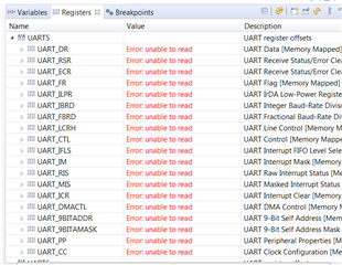
When I open the Registers window in my debug session, I don't see any registers in that window.
The breakpoint window works properly, I could see my break point there.
Thanks
Kiran
Hi Ralph,
As per your suggestions, I put a break point in my while loop.
But UART5 registers says enable to read. Any Idea why is this?
I get following. Also inserted the 3 files I changed.
Thanks
Kiran
//*****************************************************************************
//
// uart_echo.c - Example for reading data from and writing data to the UART in
//               an interrupt driven fashion.
//
// Copyright (c) 2013-2017 Texas Instruments Incorporated.  All rights reserved.
// Software License Agreement
//
// Texas Instruments (TI) is supplying this software for use solely and
// exclusively on TI's microcontroller products. The software is owned by
// TI and/or its suppliers, and is protected under applicable copyright
// laws. You may not combine this software with "viral" open-source
// software in order to form a larger program.
//
// THIS SOFTWARE IS PROVIDED "AS IS" AND WITH ALL FAULTS.
// NO WARRANTIES, WHETHER EXPRESS, IMPLIED OR STATUTORY, INCLUDING, BUT
// NOT LIMITED TO, IMPLIED WARRANTIES OF MERCHANTABILITY AND FITNESS FOR
// A PARTICULAR PURPOSE APPLY TO THIS SOFTWARE. TI SHALL NOT, UNDER ANY
// CIRCUMSTANCES, BE LIABLE FOR SPECIAL, INCIDENTAL, OR CONSEQUENTIAL
// DAMAGES, FOR ANY REASON WHATSOEVER.
//
// This is part of revision 2.1.4.178 of the DK-TM4C129X Firmware Package.
//
//*****************************************************************************

#include <stdint.h>
#include <stdbool.h>
#include "inc/hw_ints.h"
#include "inc/hw_memmap.h"
#include "inc/hw_types.h"
#include "driverlib/debug.h"
#include "driverlib/gpio.h"
#include "driverlib/interrupt.h"
#include "driverlib/sysctl.h"
#include "driverlib/uart.h"
#include "driverlib/rom.h"
#include "driverlib/rom_map.h"
#include "grlib/grlib.h"
#include "drivers/kentec320x240x16_ssd2119.h"
#include "drivers/frame.h"
#include "drivers/pinout.h"

//*****************************************************************************
//
//! \addtogroup example_list
//! <h1>UART Echo (uart_echo)</h1>
//!
//! This example application utilizes the UART to echo text.  The first UART
//! (connected to the FTDI virtual serial port on the evaluation board) will be
//! configured in 115,200 baud, 8-n-1 mode.  All characters received on the
//! UART are transmitted back to the UART.
//
//*****************************************************************************

//*****************************************************************************
//
// The error routine that is called if the driver library encounters an error.
//
//*****************************************************************************
#ifdef DEBUG
void
__error__(char *pcFilename, uint32_t ui32Line)
{
}
#endif

//*****************************************************************************
//
// The UART interrupt handler.
//
//*****************************************************************************
void
UARTIntHandler(void)
{
    uint32_t ui32Status;

    //
    // Get the interrrupt status.
    //
    ui32Status = ROM_UARTIntStatus(UART5_BASE, true);

    //
    // Clear the asserted interrupts.
    //
    ROM_UARTIntClear(UART5_BASE, ui32Status);

    //
    // Loop while there are characters in the receive FIFO.
    //
    while(ROM_UARTCharsAvail(UART5_BASE))
    {
        //
        // Read the next character from the UART and write it back to the UART.
        //
        ROM_UARTCharPutNonBlocking(UART5_BASE,
                                   UARTCharGetNonBlocking(UART5_BASE));
    }
}

//*****************************************************************************
//
// Send a string to the UART.
//
//*****************************************************************************
void
UARTSend(const uint8_t *pui8Buffer, uint32_t ui32Count)
{
    //
    // Loop while there are more characters to send.
    //
    while(ui32Count--)
    {
        //
        // Write the next character to the UART.
        //
        ROM_UARTCharPutNonBlocking(UART5_BASE, *pui8Buffer++);
    }
}

//*****************************************************************************
//
// This example demonstrates how to send a string of data to the UART.
//
//*****************************************************************************
int
main(void)
{
    volatile uint32_t ui32Loop;
    uint32_t ui32SysClock;
    tContext sContext;

    //
    // Run from the PLL at 120 MHz.
    //
   ui32SysClock = MAP_SysCtlClockFreqSet((SYSCTL_XTAL_25MHZ |
                                           SYSCTL_OSC_MAIN | SYSCTL_USE_PLL |
                                           SYSCTL_CFG_VCO_480), 120000000);

    //
    // Configure the device pins.
    //
    PinoutSet();

    //
    // Initialize the display driver.
    //
    Kentec320x240x16_SSD2119Init(ui32SysClock);

    //
    // Initialize the graphics context.
    //
    GrContextInit(&sContext, &g_sKentec320x240x16_SSD2119);

    //
    // Draw the application frame.
    //
    FrameDraw(&sContext, "uart-echo");

    //
    // Display UART configuration on the display.
    //
    GrStringDraw(&sContext, "Port:",       -1,  70, 70, 0);
    GrStringDraw(&sContext, "Baud:",       -1,  70, 95, 0);
    GrStringDraw(&sContext, "Data:",       -1,  70, 120, 0);
    GrStringDraw(&sContext, "Parity:",     -1,  70, 145, 0);
    GrStringDraw(&sContext, "Stop:",       -1,  70, 170, 0);
    GrStringDraw(&sContext, "Uart 5",      -1, 150, 70, 0);
    GrStringDraw(&sContext, "115,200 bps", -1, 150, 95, 0);
    GrStringDraw(&sContext, "8 Bit",       -1, 150, 120, 0);
    GrStringDraw(&sContext, "None",        -1, 150, 145, 0);
    GrStringDraw(&sContext, "1 Bit",       -1, 150, 170, 0);

    //
    // Enable the (non-GPIO) peripherals used by this example.  PinoutSet()
    // already enabled GPIO Port A.
    //
    ROM_SysCtlPeripheralEnable(SYSCTL_PERIPH_UART5);

    //
    // Enable processor interrupts.
    //
    IntMasterEnable();

    //
    // Configure the UART for 115,200, 8-N-1 operation.
    //
    ROM_UARTConfigSetExpClk(UART5_BASE, ui32SysClock, 115200,
                            (UART_CONFIG_WLEN_8 | UART_CONFIG_STOP_ONE |
                             UART_CONFIG_PAR_NONE));

    //
    // Enable the UART interrupt.
    //
    ROM_IntEnable(INT_UART5);
    ROM_UARTIntEnable(UART5_BASE, UART_INT_RX | UART_INT_RT);

    //
    // Prompt for text to be entered.
    //
    UARTSend((uint8_t *)"Enter text: ", 12);

    //
    // Loop forever echoing data through the UART.
    //
    while(1)
    {
        UARTSend((uint8_t *)"Enter text: ", 12);
        for(ui32Loop = 0; ui32Loop < 1340000; ui32Loop++) // 1 second ON
        {
        }
    }
}
//*****************************************************************************
//
// pinout.c - Function to configure the device pins on the DK-TM4C129X.
//
// Copyright (c) 2013-2017 Texas Instruments Incorporated.  All rights reserved.
// Software License Agreement
//
// Texas Instruments (TI) is supplying this software for use solely and
// exclusively on TI's microcontroller products. The software is owned by
// TI and/or its suppliers, and is protected under applicable copyright
// laws. You may not combine this software with "viral" open-source
// software in order to form a larger program.
//
// THIS SOFTWARE IS PROVIDED "AS IS" AND WITH ALL FAULTS.
// NO WARRANTIES, WHETHER EXPRESS, IMPLIED OR STATUTORY, INCLUDING, BUT
// NOT LIMITED TO, IMPLIED WARRANTIES OF MERCHANTABILITY AND FITNESS FOR
// A PARTICULAR PURPOSE APPLY TO THIS SOFTWARE. TI SHALL NOT, UNDER ANY
// CIRCUMSTANCES, BE LIABLE FOR SPECIAL, INCIDENTAL, OR CONSEQUENTIAL
// DAMAGES, FOR ANY REASON WHATSOEVER.
//
// This is part of revision 2.1.4.178 of the DK-TM4C129X Firmware Package.
//
//*****************************************************************************

#include <stdbool.h>
#include <stdint.h>
#include "inc/hw_gpio.h"
#include "inc/hw_memmap.h"
#include "inc/hw_types.h"
#include "driverlib/gpio.h"
#include "driverlib/pin_map.h"
#include "driverlib/rom.h"
#include "driverlib/sysctl.h"
#include "drivers/pinout.h"

//*****************************************************************************
//
//! \addtogroup pinout_api
//! @{
//
//*****************************************************************************

//*****************************************************************************
//
//! Configures the device pins for the standard usages on the DK-TM4C129X.
//!
//! This function enables the GPIO modules and configures the device pins for
//! the default, standard usages on the DK-TM4C129X.  Applications that require
//! alternate configurations of the device pins can either not call this
//! function and take full responsibility for configuring all the device pins,
//! or can reconfigure the required device pins after calling this function.
//!
//! \return None.
//
//*****************************************************************************
void
PinoutSet(void)
{
    //
    // Enable all the GPIO peripherals.
    //
    ROM_SysCtlPeripheralEnable(SYSCTL_PERIPH_GPIOA);
    ROM_SysCtlPeripheralEnable(SYSCTL_PERIPH_GPIOB);
    ROM_SysCtlPeripheralEnable(SYSCTL_PERIPH_GPIOC);
    ROM_SysCtlPeripheralEnable(SYSCTL_PERIPH_GPIOD);
    ROM_SysCtlPeripheralEnable(SYSCTL_PERIPH_GPIOE);
    ROM_SysCtlPeripheralEnable(SYSCTL_PERIPH_GPIOF);
    ROM_SysCtlPeripheralEnable(SYSCTL_PERIPH_GPIOG);
    ROM_SysCtlPeripheralEnable(SYSCTL_PERIPH_GPIOH);
    ROM_SysCtlPeripheralEnable(SYSCTL_PERIPH_GPIOJ);
    ROM_SysCtlPeripheralEnable(SYSCTL_PERIPH_GPIOK);
    ROM_SysCtlPeripheralEnable(SYSCTL_PERIPH_GPIOL);
    ROM_SysCtlPeripheralEnable(SYSCTL_PERIPH_GPIOM);
    ROM_SysCtlPeripheralEnable(SYSCTL_PERIPH_GPION);
    ROM_SysCtlPeripheralEnable(SYSCTL_PERIPH_GPIOP);
    ROM_SysCtlPeripheralEnable(SYSCTL_PERIPH_GPIOQ);
    ROM_SysCtlPeripheralEnable(SYSCTL_PERIPH_GPIOR);
    ROM_SysCtlPeripheralEnable(SYSCTL_PERIPH_GPIOS);
    ROM_SysCtlPeripheralEnable(SYSCTL_PERIPH_GPIOT);

    //
    // PA0-1 are used for UART0.
    //
 //   ROM_GPIOPinConfigure(GPIO_PA0_U0RX);
 //   ROM_GPIOPinConfigure(GPIO_PA1_U0TX);
 //   ROM_GPIOPinTypeUART(GPIO_PORTA_BASE, GPIO_PIN_0 | GPIO_PIN_1);

    //
    // PB0-1 are used for UART1.
    //
//    ROM_GPIOPinConfigure(GPIO_PB0_U1RX);
//    ROM_GPIOPinConfigure(GPIO_PB1_U1TX);
//    ROM_GPIOPinTypeUART(GPIO_PORTB_BASE, GPIO_PIN_0 | GPIO_PIN_1);
    //
    // PC6/PH7 are used for UART5.
    //
    ROM_GPIOPinConfigure(GPIO_PC6_U5RX);
    ROM_GPIOPinConfigure(GPIO_PH7_U5TX);
    ROM_GPIOPinTypeUART(GPIO_PORTC_BASE, GPIO_PIN_6);
    ROM_GPIOPinTypeUART(GPIO_PORTH_BASE, GPIO_PIN_7);

    //
    // PA2-5 are used for SSI0 to the second booster pack.
    //
    ROM_GPIOPinConfigure(GPIO_PA2_SSI0CLK);
    ROM_GPIOPinConfigure(GPIO_PA3_SSI0FSS);
    ROM_GPIOPinConfigure(GPIO_PA4_SSI0XDAT0);
    ROM_GPIOPinConfigure(GPIO_PA5_SSI0XDAT1);

    //
    // PB0-1/PD6-7/PL6-7 are used for USB.
    //
    HWREG(GPIO_PORTD_BASE + GPIO_O_LOCK) = GPIO_LOCK_KEY;
    HWREG(GPIO_PORTD_BASE + GPIO_O_CR) = 0xff;
    ROM_GPIOPinConfigure(GPIO_PD6_USB0EPEN);
    ROM_GPIOPinConfigure(GPIO_PD7_USB0PFLT);
    ROM_GPIOPinTypeUSBAnalog(GPIO_PORTB_BASE, GPIO_PIN_0 | GPIO_PIN_1);
    ROM_GPIOPinTypeUSBDigital(GPIO_PORTD_BASE, GPIO_PIN_6 | GPIO_PIN_7);
    ROM_GPIOPinTypeUSBAnalog(GPIO_PORTL_BASE, GPIO_PIN_6 | GPIO_PIN_7);

    //
    // PB2/PD4 are used for the speaker output.
    //
    ROM_GPIOPinConfigure(GPIO_PB2_T5CCP0);
    ROM_GPIOPinTypeTimer(GPIO_PORTB_BASE, GPIO_PIN_2);
    ROM_GPIOPinTypeGPIOOutput(GPIO_PORTD_BASE, GPIO_PIN_4);
    ROM_GPIOPinWrite(GPIO_PORTD_BASE, GPIO_PIN_4, 0);

    //
    // PB6-7 are used for I2C to the TMP100 and the EM connector.
    //
    ROM_GPIOPinConfigure(GPIO_PB6_I2C6SCL);
    ROM_GPIOPinConfigure(GPIO_PB7_I2C6SDA);
    ROM_GPIOPinTypeI2CSCL(GPIO_PORTB_BASE, GPIO_PIN_6);
    ROM_GPIOPinTypeI2C(GPIO_PORTB_BASE, GPIO_PIN_7);

    //
    // PE5/PN3/PP1 are used for the push buttons.
    //
    ROM_GPIOPinTypeGPIOInput(GPIO_PORTE_BASE, GPIO_PIN_5);
    ROM_GPIOPinTypeGPIOInput(GPIO_PORTN_BASE, GPIO_PIN_3);
    ROM_GPIOPinTypeGPIOInput(GPIO_PORTP_BASE, GPIO_PIN_1);

    //
    // PE7/PP7/PT2-3 are used for the touch screen.
    //
    HWREG(GPIO_PORTE_BASE + GPIO_O_LOCK) = GPIO_LOCK_KEY;
    HWREG(GPIO_PORTE_BASE + GPIO_O_CR) = 0xff;
    ROM_GPIOPinTypeGPIOInput(GPIO_PORTE_BASE, GPIO_PIN_7);
    ROM_GPIOPinTypeGPIOInput(GPIO_PORTP_BASE, GPIO_PIN_7);
    ROM_GPIOPinTypeGPIOInput(GPIO_PORTT_BASE, GPIO_PIN_2 | GPIO_PIN_3);
    ROM_GPIOPinTypeGPIOOutput(GPIO_PORTE_BASE, GPIO_PIN_7);
    ROM_GPIOPinWrite(GPIO_PORTE_BASE, GPIO_PIN_7, 0);
    ROM_GPIOPinTypeGPIOOutput(GPIO_PORTP_BASE, GPIO_PIN_7);
    ROM_GPIOPinWrite(GPIO_PORTP_BASE, GPIO_PIN_7, 0);
    ROM_GPIOPinTypeGPIOOutput(GPIO_PORTT_BASE, GPIO_PIN_2 | GPIO_PIN_3);
    ROM_GPIOPinWrite(GPIO_PORTT_BASE, GPIO_PIN_2 | GPIO_PIN_3, 0);

    //
    // PF0/PF4-5/PH4/PQ0-2 are used for the SPI flash (on-board and SD card).
    // PH4 selects the SD card and PQ1 selects the on-board SPI flash.
    //
    ROM_GPIOPinConfigure(GPIO_PF0_SSI3XDAT1);
    ROM_GPIOPinConfigure(GPIO_PF4_SSI3XDAT2);
    ROM_GPIOPinConfigure(GPIO_PF5_SSI3XDAT3);
    ROM_GPIOPinConfigure(GPIO_PQ0_SSI3CLK);
    ROM_GPIOPinConfigure(GPIO_PQ2_SSI3XDAT0);
    ROM_GPIOPinTypeSSI(GPIO_PORTF_BASE, GPIO_PIN_0 | GPIO_PIN_4 | GPIO_PIN_5);
    ROM_GPIOPinTypeGPIOOutput(GPIO_PORTH_BASE, GPIO_PIN_4);
    ROM_GPIOPinWrite(GPIO_PORTH_BASE, GPIO_PIN_4, GPIO_PIN_4);
    ROM_GPIOPinTypeSSI(GPIO_PORTQ_BASE, GPIO_PIN_0 | GPIO_PIN_2);
    ROM_GPIOPinTypeGPIOOutput(GPIO_PORTQ_BASE, GPIO_PIN_1);
    ROM_GPIOPinWrite(GPIO_PORTQ_BASE, GPIO_PIN_1, GPIO_PIN_1);

    //
    // PF1/PK4/PK6 are used for Ethernet LEDs.
    //
    ROM_GPIOPinConfigure(GPIO_PF1_EN0LED2);
    ROM_GPIOPinConfigure(GPIO_PK4_EN0LED0);
    ROM_GPIOPinConfigure(GPIO_PK6_EN0LED1);
    GPIOPinTypeEthernetLED(GPIO_PORTF_BASE, GPIO_PIN_1);
    GPIOPinTypeEthernetLED(GPIO_PORTK_BASE, GPIO_PIN_4);
    GPIOPinTypeEthernetLED(GPIO_PORTK_BASE, GPIO_PIN_6);

    //
    // PF6-7/PJ6/PS4-5/PR0-7 are used for the LCD.
    //
    ROM_GPIOPinConfigure(GPIO_PF7_LCDDATA02);
    ROM_GPIOPinConfigure(GPIO_PJ6_LCDAC);
    ROM_GPIOPinConfigure(GPIO_PR0_LCDCP);
    ROM_GPIOPinConfigure(GPIO_PR1_LCDFP);
    ROM_GPIOPinConfigure(GPIO_PR2_LCDLP);
    ROM_GPIOPinConfigure(GPIO_PR3_LCDDATA03);
    ROM_GPIOPinConfigure(GPIO_PR4_LCDDATA00);
    ROM_GPIOPinConfigure(GPIO_PR5_LCDDATA01);
    ROM_GPIOPinConfigure(GPIO_PR6_LCDDATA04);
    ROM_GPIOPinConfigure(GPIO_PR7_LCDDATA05);
    ROM_GPIOPinConfigure(GPIO_PS4_LCDDATA06);
    ROM_GPIOPinConfigure(GPIO_PS5_LCDDATA07);
    ROM_GPIOPinTypeGPIOOutput(GPIO_PORTF_BASE, GPIO_PIN_6);
    ROM_GPIOPinWrite(GPIO_PORTF_BASE, GPIO_PIN_6, GPIO_PIN_6);
    GPIOPinTypeLCD(GPIO_PORTF_BASE, GPIO_PIN_7);
    GPIOPinTypeLCD(GPIO_PORTJ_BASE, GPIO_PIN_6);
    GPIOPinTypeLCD(GPIO_PORTR_BASE,
                       (GPIO_PIN_0 | GPIO_PIN_1 | GPIO_PIN_2 | GPIO_PIN_3 |
                        GPIO_PIN_4 | GPIO_PIN_5 | GPIO_PIN_6 | GPIO_PIN_7));
    GPIOPinTypeLCD(GPIO_PORTS_BASE, GPIO_PIN_4 | GPIO_PIN_5);

    //
    // PQ7 is used for the user LED.
    //
    ROM_GPIOPinTypeGPIOOutput(GPIO_PORTQ_BASE, GPIO_PIN_7);
    ROM_GPIOPinWrite(GPIO_PORTQ_BASE, GPIO_PIN_7, 0);
}

//*****************************************************************************
//
//! Configures the USB pins for ULPI connection to an external USB PHY.
//!
//! This function configures the USB ULPI pins to connect the DK-TM4C129X board
//! to an external USB PHY in ULPI mode.  This allows the external PHY to act
//! as an external high-speed phy for the DK-TM4C129X.  This function must be
//! called after the call to PinoutSet() to properly configure the pins.
//!
//! \return None.
//
//*****************************************************************************
#ifdef USE_ULPI
void
USBULPIPinoutSet(void)
{
    //
    // Enable all the peripherals that are used by the ULPI interface.
    //
    ROM_SysCtlPeripheralEnable(SYSCTL_PERIPH_GPIOB);
    ROM_SysCtlPeripheralEnable(SYSCTL_PERIPH_GPIOL);
    ROM_SysCtlPeripheralEnable(SYSCTL_PERIPH_GPIOM);
    ROM_SysCtlPeripheralEnable(SYSCTL_PERIPH_GPIOP);

    //
    // ULPI Port B pins.
    //
    ROM_GPIOPinConfigure(GPIO_PB2_USB0STP);
    ROM_GPIOPinConfigure(GPIO_PB3_USB0CLK);
    ROM_GPIOPinTypeUSBDigital(GPIO_PORTB_BASE, GPIO_PIN_2 | GPIO_PIN_3);
    GPIOPadConfigSet(GPIO_PORTB_BASE, GPIO_PIN_2 | GPIO_PIN_3,
                     GPIO_STRENGTH_12MA, GPIO_PIN_TYPE_STD);

    //
    // ULPI Port P pins.
    //
    ROM_GPIOPinConfigure(GPIO_PP2_USB0NXT);
    ROM_GPIOPinConfigure(GPIO_PP3_USB0DIR);
    ROM_GPIOPinConfigure(GPIO_PP4_USB0D7);
    ROM_GPIOPinConfigure(GPIO_PP5_USB0D6);
    ROM_GPIOPinTypeUSBDigital(GPIO_PORTP_BASE, GPIO_PIN_2 | GPIO_PIN_3 |
                                               GPIO_PIN_4 | GPIO_PIN_5);
    GPIOPadConfigSet(GPIO_PORTP_BASE,
                     GPIO_PIN_2 | GPIO_PIN_3 | GPIO_PIN_4 | GPIO_PIN_5,
                     GPIO_STRENGTH_12MA, GPIO_PIN_TYPE_STD);

    //
    // ULPI Port L pins.
    //
    ROM_GPIOPinConfigure(GPIO_PL5_USB0D5);
    ROM_GPIOPinConfigure(GPIO_PL4_USB0D4);
    ROM_GPIOPinConfigure(GPIO_PL3_USB0D3);
    ROM_GPIOPinConfigure(GPIO_PL2_USB0D2);
    ROM_GPIOPinConfigure(GPIO_PL1_USB0D1);
    ROM_GPIOPinConfigure(GPIO_PL0_USB0D0);
    ROM_GPIOPinTypeUSBDigital(GPIO_PORTL_BASE, GPIO_PIN_0 | GPIO_PIN_1 |
                                               GPIO_PIN_2 | GPIO_PIN_3 |
                                               GPIO_PIN_4 | GPIO_PIN_5);
    GPIOPadConfigSet(GPIO_PORTL_BASE,
                     GPIO_PIN_0 | GPIO_PIN_1 | GPIO_PIN_2 | GPIO_PIN_3 |
                     GPIO_PIN_4 | GPIO_PIN_5,
                     GPIO_STRENGTH_12MA, GPIO_PIN_TYPE_STD);
    //
    // ULPI Port M pins used to control the external USB oscillator and the
    // external USB phy on the DK-TM4C129X-DPHY board.
    //
    // PM1 - Enables the USB oscillator on the DK-TM4C129X-DPHY board.
    // PM3 - Enables the USB phy on the DK-TM4C129X-DPHY board.
    //
    ROM_GPIOPinTypeGPIOOutput(GPIO_PORTM_BASE, GPIO_PIN_1 | GPIO_PIN_3);
    ROM_GPIOPinWrite(GPIO_PORTM_BASE, GPIO_PIN_1 | GPIO_PIN_3, GPIO_PIN_1 |
                                                               GPIO_PIN_3);
}
#endif

//*****************************************************************************
//
// Close the Doxygen group.
//! @}
//
//*****************************************************************************
//*****************************************************************************
//
// startup_ccs.c - Startup code for use with TI's Code Composer Studio.
//
// Copyright (c) 2013-2017 Texas Instruments Incorporated.  All rights reserved.
// Software License Agreement
//
// Texas Instruments (TI) is supplying this software for use solely and
// exclusively on TI's microcontroller products. The software is owned by
// TI and/or its suppliers, and is protected under applicable copyright
// laws. You may not combine this software with "viral" open-source
// software in order to form a larger program.
//
// THIS SOFTWARE IS PROVIDED "AS IS" AND WITH ALL FAULTS.
// NO WARRANTIES, WHETHER EXPRESS, IMPLIED OR STATUTORY, INCLUDING, BUT
// NOT LIMITED TO, IMPLIED WARRANTIES OF MERCHANTABILITY AND FITNESS FOR
// A PARTICULAR PURPOSE APPLY TO THIS SOFTWARE. TI SHALL NOT, UNDER ANY
// CIRCUMSTANCES, BE LIABLE FOR SPECIAL, INCIDENTAL, OR CONSEQUENTIAL
// DAMAGES, FOR ANY REASON WHATSOEVER.
//
// This is part of revision 2.1.4.178 of the DK-TM4C129X Firmware Package.
//
//*****************************************************************************

#include <stdint.h>
#include "inc/hw_nvic.h"
#include "inc/hw_types.h"

//*****************************************************************************
//
// Forward declaration of the default fault handlers.
//
//*****************************************************************************
void ResetISR(void);
static void NmiSR(void);
static void FaultISR(void);
static void IntDefaultHandler(void);

//*****************************************************************************
//
// External declaration for the reset handler that is to be called when the
// processor is started
//
//*****************************************************************************
extern void _c_int00(void);

//*****************************************************************************
//
// Linker variable that marks the top of the stack.
//
//*****************************************************************************
extern uint32_t __STACK_TOP;

//*****************************************************************************
//
// External declaration for the interrupt handler used by the application.
//
//*****************************************************************************
extern void UARTIntHandler(void);

//*****************************************************************************
//
// The vector table.  Note that the proper constructs must be placed on this to
// ensure that it ends up at physical address 0x0000.0000 or at the start of
// the program if located at a start address other than 0.
//
//*****************************************************************************
#pragma DATA_SECTION(g_pfnVectors, ".intvecs")
void (* const g_pfnVectors[])(void) =
{
    (void (*)(void))((uint32_t)&__STACK_TOP),
                                            // The initial stack pointer
    ResetISR,                               // The reset handler
    NmiSR,                                  // The NMI handler
    FaultISR,                               // The hard fault handler
    IntDefaultHandler,                      // The MPU fault handler
    IntDefaultHandler,                      // The bus fault handler
    IntDefaultHandler,                      // The usage fault handler
    0,                                      // Reserved
    0,                                      // Reserved
    0,                                      // Reserved
    0,                                      // Reserved
    IntDefaultHandler,                      // SVCall handler
    IntDefaultHandler,                      // Debug monitor handler
    0,                                      // Reserved
    IntDefaultHandler,                      // The PendSV handler
    IntDefaultHandler,                      // The SysTick handler
    IntDefaultHandler,                      // GPIO Port A
    IntDefaultHandler,                      // GPIO Port B
    IntDefaultHandler,                      // GPIO Port C
    IntDefaultHandler,                      // GPIO Port D
    IntDefaultHandler,                      // GPIO Port E
    IntDefaultHandler,                         // UART0 Rx and Tx
    IntDefaultHandler,                      // UART1 Rx and Tx
    IntDefaultHandler,                      // SSI0 Rx and Tx
    IntDefaultHandler,                      // I2C0 Master and Slave
    IntDefaultHandler,                      // PWM Fault
    IntDefaultHandler,                      // PWM Generator 0
    IntDefaultHandler,                      // PWM Generator 1
    IntDefaultHandler,                      // PWM Generator 2
    IntDefaultHandler,                      // Quadrature Encoder 0
    IntDefaultHandler,                      // ADC Sequence 0
    IntDefaultHandler,                      // ADC Sequence 1
    IntDefaultHandler,                      // ADC Sequence 2
    IntDefaultHandler,                      // ADC Sequence 3
    IntDefaultHandler,                      // Watchdog timer
    IntDefaultHandler,                      // Timer 0 subtimer A
    IntDefaultHandler,                      // Timer 0 subtimer B
    IntDefaultHandler,                      // Timer 1 subtimer A
    IntDefaultHandler,                      // Timer 1 subtimer B
    IntDefaultHandler,                      // Timer 2 subtimer A
    IntDefaultHandler,                      // Timer 2 subtimer B
    IntDefaultHandler,                      // Analog Comparator 0
    IntDefaultHandler,                      // Analog Comparator 1
    IntDefaultHandler,                      // Analog Comparator 2
    IntDefaultHandler,                      // System Control (PLL, OSC, BO)
    IntDefaultHandler,                      // FLASH Control
    IntDefaultHandler,                      // GPIO Port F
    IntDefaultHandler,                      // GPIO Port G
    IntDefaultHandler,                      // GPIO Port H
    IntDefaultHandler,                      // UART2 Rx and Tx
    IntDefaultHandler,                      // SSI1 Rx and Tx
    IntDefaultHandler,                      // Timer 3 subtimer A
    IntDefaultHandler,                      // Timer 3 subtimer B
    IntDefaultHandler,                      // I2C1 Master and Slave
    IntDefaultHandler,                      // CAN0
    IntDefaultHandler,                      // CAN1
    IntDefaultHandler,                      // Ethernet
    IntDefaultHandler,                      // Hibernate
    IntDefaultHandler,                      // USB0
    IntDefaultHandler,                      // PWM Generator 3
    IntDefaultHandler,                      // uDMA Software Transfer
    IntDefaultHandler,                      // uDMA Error
    IntDefaultHandler,                      // ADC1 Sequence 0
    IntDefaultHandler,                      // ADC1 Sequence 1
    IntDefaultHandler,                      // ADC1 Sequence 2
    IntDefaultHandler,                      // ADC1 Sequence 3
    IntDefaultHandler,                      // External Bus Interface 0
    IntDefaultHandler,                      // GPIO Port J
    IntDefaultHandler,                      // GPIO Port K
    IntDefaultHandler,                      // GPIO Port L
    IntDefaultHandler,                      // SSI2 Rx and Tx
    IntDefaultHandler,                      // SSI3 Rx and Tx
    IntDefaultHandler,                      // UART3 Rx and Tx
    IntDefaultHandler,                      // UART4 Rx and Tx
    UARTIntHandler,                      // UART5 Rx and Tx
    IntDefaultHandler,                      // UART6 Rx and Tx
    IntDefaultHandler,                      // UART7 Rx and Tx
    IntDefaultHandler,                      // I2C2 Master and Slave
    IntDefaultHandler,                      // I2C3 Master and Slave
    IntDefaultHandler,                      // Timer 4 subtimer A
    IntDefaultHandler,                      // Timer 4 subtimer B
    IntDefaultHandler,                      // Timer 5 subtimer A
    IntDefaultHandler,                      // Timer 5 subtimer B
    IntDefaultHandler,                      // FPU
    0,                                      // Reserved
    0,                                      // Reserved
    IntDefaultHandler,                      // I2C4 Master and Slave
    IntDefaultHandler,                      // I2C5 Master and Slave
    IntDefaultHandler,                      // GPIO Port M
    IntDefaultHandler,                      // GPIO Port N
    0,                                      // Reserved
    IntDefaultHandler,                      // Tamper
    IntDefaultHandler,                      // GPIO Port P (Summary or P0)
    IntDefaultHandler,                      // GPIO Port P1
    IntDefaultHandler,                      // GPIO Port P2
    IntDefaultHandler,                      // GPIO Port P3
    IntDefaultHandler,                      // GPIO Port P4
    IntDefaultHandler,                      // GPIO Port P5
    IntDefaultHandler,                      // GPIO Port P6
    IntDefaultHandler,                      // GPIO Port P7
    IntDefaultHandler,                      // GPIO Port Q (Summary or Q0)
    IntDefaultHandler,                      // GPIO Port Q1
    IntDefaultHandler,                      // GPIO Port Q2
    IntDefaultHandler,                      // GPIO Port Q3
    IntDefaultHandler,                      // GPIO Port Q4
    IntDefaultHandler,                      // GPIO Port Q5
    IntDefaultHandler,                      // GPIO Port Q6
    IntDefaultHandler,                      // GPIO Port Q7
    IntDefaultHandler,                      // GPIO Port R
    IntDefaultHandler,                      // GPIO Port S
    IntDefaultHandler,                      // SHA/MD5 0
    IntDefaultHandler,                      // AES 0
    IntDefaultHandler,                      // DES3DES 0
    IntDefaultHandler,                      // LCD Controller 0
    IntDefaultHandler,                      // Timer 6 subtimer A
    IntDefaultHandler,                      // Timer 6 subtimer B
    IntDefaultHandler,                      // Timer 7 subtimer A
    IntDefaultHandler,                      // Timer 7 subtimer B
    IntDefaultHandler,                      // I2C6 Master and Slave
    IntDefaultHandler,                      // I2C7 Master and Slave
    IntDefaultHandler,                      // HIM Scan Matrix Keyboard 0
    IntDefaultHandler,                      // One Wire 0
    IntDefaultHandler,                      // HIM PS/2 0
    IntDefaultHandler,                      // HIM LED Sequencer 0
    IntDefaultHandler,                      // HIM Consumer IR 0
    IntDefaultHandler,                      // I2C8 Master and Slave
    IntDefaultHandler,                      // I2C9 Master and Slave
    IntDefaultHandler                       // GPIO Port T
};

//*****************************************************************************
//
// This is the code that gets called when the processor first starts execution
// following a reset event.  Only the absolutely necessary set is performed,
// after which the application supplied entry() routine is called.  Any fancy
// actions (such as making decisions based on the reset cause register, and
// resetting the bits in that register) are left solely in the hands of the
// application.
//
//*****************************************************************************
void
ResetISR(void)
{
    //
    // Jump to the CCS C initialization routine.  This will enable the
    // floating-point unit as well, so that does not need to be done here.
    //
    __asm("    .global _c_int00\n"
          "    b.w     _c_int00");
}

//*****************************************************************************
//
// This is the code that gets called when the processor receives a NMI.  This
// simply enters an infinite loop, preserving the system state for examination
// by a debugger.
//
//*****************************************************************************
static void
NmiSR(void)
{
    //
    // Enter an infinite loop.
    //
    while(1)
    {
    }
}

//*****************************************************************************
//
// This is the code that gets called when the processor receives a fault
// interrupt.  This simply enters an infinite loop, preserving the system state
// for examination by a debugger.
//
//*****************************************************************************
static void
FaultISR(void)
{
    //
    // Enter an infinite loop.
    //
    while(1)
    {
    }
}

//*****************************************************************************
//
// This is the code that gets called when the processor receives an unexpected
// interrupt.  This simply enters an infinite loop, preserving the system state
// for examination by a debugger.
//
//*****************************************************************************
static void
IntDefaultHandler(void)
{
    //
    // Go into an infinite loop.
    //
    while(1)
    {
    }
}
Hello Kiran,
Is there any indication of an error with the debugger? Like in an unusual memory location, hit FaultISR, etc.?
What are your optimization settings?
Are you using a debug or protection release?
Rather than files if you could attach the whole CCS project, they would then include your project settings. Not sure if that's viable for you, understand if not due to other software that may be included.
Best Regards,
Ralph Jacobi
Hi Ralph,
Debugger doesn't show any error.
I am using default optimization settings.
I am using a debug release.
I am attaching the complete project zip file.
Thanks
Kiran5810.uart_echo.zip
Hello Kiran,
That is a bit strange. I will have to try it again tomorrow because I only have a board with XDS200 programming handy right now but it was running fine for me. I could see registers and I got the right output:

Best Regards,
Ralph Jacobi
Hello Kiran,
I'm not really sure what to suggest on my end right now. Using ICDI I was able to debug your project as expected, and I confirmed the outputs. To be everything seems to be configured fine.
The only thing I had to change was default library location because I didn't have your local TI REX download, so I pointed it to TivaWare 2.2.0.295 on my C drive.
Best Regards,
Ralph Jacobi