This thread has been locked.

If you have a related question, please click the "Ask a related question" button in the top right corner. The newly created question will be automatically linked to this question.

TMS570LC4357: SPI communication problem in the tmdx570lc43hdk Evaluation Board

Part Number: TMS570LC4357
Other Parts Discussed in Thread: TMDX570LC43HDK, HALCOGEN

Hello

Hardware:

tmdx570lc43hdk evaluation board

Software:

Generate the driver code by the HCG software tool.

Question:

(1) By monitoring the CS pin with an oscilloscope, I found that it was always pulled down.

(2)  Only when “spiSendAndGetData” Function is called again will the CLK pin be detected. 

Later, I found that in the “spisenddata” function, only the transmit interrupt flag bit is set, and then the transmit and receive interrupt flag bits are set in the spiSendAndGetData” function.

(3) If it didn't set use the receive interrupt , the CLK can't be detected.

  • Hi Wanzhao,

    1. The CS pin should be pulled high when the transfer is done. During the data transmission, the CS pin is pulled down.

    2. The SPI clock is not a free-running clock signal. The SPI generates the SPI clock only when the data is written to SPIDAT register.

         The spiSendData() is used to transmits data using interrupt method, so only TX interrupt is enabled. The spiSendAndGetData is to transmit data transmit data and receive data in interrupt mode, so the both TX and RX interrupt are enabled. 

    3. The SPI clock is generated by SPI master when data is written to SPIDAT register. I don't fully understand your question.

  • hello Wang

    I can understand your reply, but it can't resolve my problem.

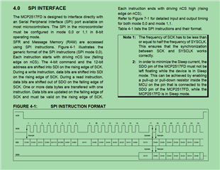
    I want to connect the MCP2517FD controller by the SPI bus. the below is the SPI interface requirement.

    (1) I try it as the attachment code , but it failed. can you tell me how to configure the SPI port by the HALCoGen tool?1346.tms570lc4357_spitest.rar

    (2) I noticed that it require the "8-bit operate mode". I set the charlen = 8 by the HALCoGen, but the API of send and receive in the code that is generated also used the "uint16_t". so how I can use the API? can you give me a example?

  • Hi Wanzhao,

    2. We noticed this issue. Please replace uint16_t with uint8_t manually.

  • hello 

    according to the code as following:

        uint16_t send_data[6] = {0};
        uint16_t recv_data[6] = {0};
        spiDAT1_t dataconfig_t;
    
        dataconfig_t.CS_HOLD = FALSE;      //CS not set hold mode
        dataconfig_t.WDEL    = TRUE;       //set delay time
        dataconfig_t.DFSEL   = SPI_FMT_0;  //default frame 0
        dataconfig_t.CSNR    = 0xFE;       //default CS0
    
    
        send_data[0] = 0x0021;
        send_data[1] = 0x00F0;
        send_data[2] = 0x007F;
        send_data[3] = 0x007F;
        send_data[4] = 0x007F;
        send_data[5] = 0x007F;
    
    
        muxInit();
        spiInit();
        _enable_interrupt_();
    
    
        while(1)
        {
    
            DELAY();
            spiSendAndGetData(spiREG2, &dataconfig_t, 6, send_data, recv_data);
            DELAY();
            DELAY();
        }

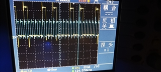
    I find it only send the first data "0021" according to the Oscilloscope.

    another problem:

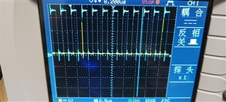
    I find that it will set the CS is high when one byte is send, like the picture

    can you help me find the reason?

  • I find it only send the first data "0021" according to the Oscilloscope.

    From the screenshot, I saw 24 clock pulse which means 3 bytes of data is transferred.

    I find that it will set the CS is high when one byte is send, like the picture

    If the CSHOLD is not set, the CS becomes HIGH between two transfers. 

  • Hello Wang

    I find it only send the first data "0021" according to the Oscilloscope.

    From the screenshot, I saw 24 clock pulse which means 3 bytes of data is transferred.

    yes, it transfer many bytes of data, but it transfer the same data. I hope it transfer 6 bytes different data as the program.

    I find that it will set the CS is high when one byte is send, like the picture

    If the CSHOLD is not set, the CS becomes HIGH between two transfers. 

    I hope one transfer can send 6 bytes data, but it only send 1 byte data. so I think the interval between two transfers should be 8*6=48 CLKs.

    summary,  I hope transfer 6 bytes data one time by the API "spiSendAndGetData". when start of the transfer the CS is low, end of the transfer the CS is high. can you tell me how to implement it or how to configure the HALCoGen?

    thanks very much!