


Part Number: SIMPLELINK-MSP432-SDK
Hi, I am trying to figure out why my SPI timing diagram looks like below:
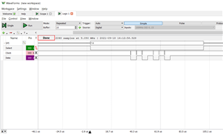
As you can see, the clocks don't look proper and there are not even enough of them.
Here is my SPI config code for EUSCI_B0:
static const eUSCI_SPI_MasterConfig SD_SPI_Config =
{
     EUSCI_B_SPI_CLOCKSOURCE_SMCLK,
     3000000,   //Source clk (SMCLK) speed
     200000,    //Desired SPI clk spd
     EUSCI_SPI_MSB_FIRST,
     EUSCI_SPI_PHASE_DATA_CAPTURED_ONFIRST_CHANGED_ON_NEXT,
     EUSCI_SPI_CLOCKPOLARITY_INACTIVITY_LOW,
     EUSCI_SPI_3PIN
};

static void power_on (void)
{

    UCB0CTLW0 |= BIT0; //UCSWRST = 1    //SPI_disableModule()?


	/* Configure MOSI/MISO/SCLK/CS pins */
	/*
	 * eUSCI B0:
	 *
	 * OUT - MOSI: P1.6
	 * IN  - MISO: P1.7
	 * OUT - SCLK: P1.5
	 * OUT - CS  : P4.6
	 * IN  - CD  : P4.7
	 */

    P4->OUT |= BIT6;            //Set CS default value to high

    P4->DIR |= BIT6;            //Set CS as output
    //P4->DIR &= ~BIT7;           //Set CD (card detect) as input

    P1SEL1 &= (~BIT7 & ~BIT6 & ~BIT5);
    P1SEL0 |= BIT7 | BIT6 | BIT5;       //Set SPI pins to use primary function instead of GPIO

    //debug: add pullup resistor to MISO
    //P1->OUT |= BIT7;
    //P1->REN |= BIT7;


    SPI_initMaster(EUSCI_B0_BASE, &SD_SPI_Config);  //Set eUSCI B0 SPI registers

    UCB0CTLW0 &= ~BIT0; //UCSWRST = 0   //SPI_enableModule()?
}
And here is my SPI transfer function:
/* Exchange a byte */

static
BYTE xchg_spi (		/* Returns received data */
	BYTE dat		/* Data to be sent */
)
{
	SPI_transmitData(EUSCI_B0_BASE, dat);
	while(!EUSCI_B_SPI_getInterruptStatus(EUSCI_B0_BASE, EUSCI_B_SPI_RECEIVE_INTERRUPT));
	//while(EUSCI_B_SPI_isBusy(EUSCI_B0_BASE));

	return EUSCI_B_SPI_receiveData(EUSCI_B0_BASE);

}
And lastly, here is my driver code:
power_on();

while(1){
    CS_LOW();   //Chip select goes low
    xchg_spi(0xAA);
    CS_HIGH();  //Chip select goes high
}
Also for background, while I don't think this should matter, I am trying to initialize/communicate with a MMC card in SPI mode. I am trying first to ensure that I am using SPI correctly.
Any ideas for what could be going wrong?
