This thread has been locked.

If you have a related question, please click the "Ask a related question" button in the top right corner. The newly created question will be automatically linked to this question.

TMS570LS1224: MibSPI daisy chain problem

Part Number: TMS570LS1224
Other Parts Discussed in Thread: UCC5870-Q1, HALCOGEN

I am using UCC5870-Q1 with TMS570LS1224PGE device. I tried configuring the MibSPI through HalCogen and code composer studio for SPI daisy chained slave devices. 

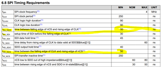
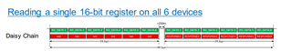
According to the datasheet, the SPI daisy chain needs to be as given in the below image. I am not able to produce the SDI line output according to the datasheet. 

Please tell me how to use HalCoGen and CCS to configure for transmitting data for SPI daisy chain. 

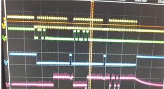
I am getting the following output instead of the one required for SPI daisy chain configuration.

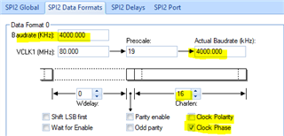
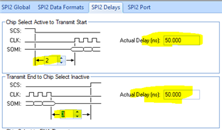
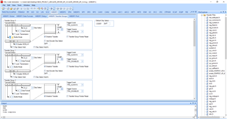
HalCoGen Initialization 

CCS CODE:

/* USER CODE BEGIN (0) */
/* USER CODE END */

/* Include Files */

#include "sys_common.h"

/* USER CODE BEGIN (1) */
#include "mibspi.h"
/* USER CODE END */

/** @fn void main(void)
* @brief Application main function
* @note This function is empty by default.
*
* This function is called after startup.
* The user can use this function to implement the application.
*/

/* USER CODE BEGIN (2) */
/* USER CODE END */

int main(void)
{
/* USER CODE BEGIN (3) */
uint16_t txBuffer[] = {0XB900, 0XB900, 0XB900, 0XB900, 0XB900, 0XB900, 0XB900, 0XB900, 0XB900, 0XB900}; //{0x0001, 0x0002, 0x0003, 0x0004, 0x0001, 0x0001, 0x0001, 0x0001, 0x0001, 0x0001} ;

mibspiInit(); /*initialize the spi */

// mibspiEnableLoopback(mibspiREG1, Digital_Lbk);

mibspiSetData(mibspiREG1, 0, txBuffer);

mibspiTransfer(mibspiREG1, 0);


while(1);
/* USER CODE END */

}

  • Hi,

    For SPI daisy-chain configuration, the six SPI devices share the same SPI_CLK, SPI_CS. The SDI and SDO should be connected as below:

    The MCU SPI_SIMO --> DSI Device1 SDO --> SDI Device 2 SDO --> ... -->SDI Device 6 SDO --> MCU SPI_SOMI.

  • According to our configuration, three SPI slave devices are present. 

    MCU SPI_SIMO -->Device1 SDI1

    Device 1 SDO --> Device 2 SDI 

    Device 2 SDO --> Device 3 SDI

    Device 3 SDO --> MCU SPI_MOSI

    Let me know how to configure HalCoGEN and CCS to achieve this.

  • There is no special HALCoGen Configuration for SPI daisy-chain setup. From TMS570 point of view, it doesn't know if the device is daisy-chain or not. You can use the same SPI data transmit API for send data to the daisy-chain devices.

    The UCC5870 follows a 16-bit protocol, utilizing specific command data frames, and communicates at rates up to 4MHz. The communication frame starts with the nCS falling edge and ends with nCS rising edge. The SPI clock idles at 0 (CPOL=0) and clocks the SDI/SDO data (CPHA=1) on the falling edge.

    The UCC5870 has special timing requirement listed in Table 6-1:

    You can use HAlCoGen to adjust the delay in TMS570 side:

    The 16-bit data frame includes three data fields: chip address (CHIP_ADDR), command type (CMD), and an 8-bit data (DATA). The chip address (CHIP_ADDR) bits are used, regardless of the system configuration. However, when using the Daisy Chain or Independent Slave configurations, 0x0 or 0xF is used for all of the devices in the system. 

    Please refer to UCC5870 datasheet regarding the data frame.

  • Thanks for your reply Wang. Can I please get CCS code for implementation of the same ?

  • Hi Sakthi,

    I don't have it. You can use the HALCoGen to generate the code.