Hi all,
I'm an engineering student who has some experience programming arduinos. I've had a project involving an EK-TM4C123GXL thrown on me. My goal is to set up the EK-TM4C123GXL as an SPI slave and an Arduino Mega 2560 as an SPI master. I've read through the user manual and a lot of other E2E posts, but I'm having no luck sending anything from the Arduino to the EK-TM4C123GXL. I've attached my code I have for both the Arduino and the EK-TM4C123GXL below. If someone could point out what I'm doing wrong, I would appreciate it. Just from using print statements, it looks like the EK-TM4C123GXL code doesn't execute past initiating SSI2.
//*****************************************************************************
//
// project0.c - Example to demonstrate minimal TivaWare setup
//
// Copyright (c) 2012-2020 Texas Instruments Incorporated. All rights reserved.
// Software License Agreement
//
// Texas Instruments (TI) is supplying this software for use solely and
// exclusively on TI's microcontroller products. The software is owned by
// TI and/or its suppliers, and is protected under applicable copyright
// laws. You may not combine this software with "viral" open-source
// software in order to form a larger program.
//
// THIS SOFTWARE IS PROVIDED "AS IS" AND WITH ALL FAULTS.
// NO WARRANTIES, WHETHER EXPRESS, IMPLIED OR STATUTORY, INCLUDING, BUT
// NOT LIMITED TO, IMPLIED WARRANTIES OF MERCHANTABILITY AND FITNESS FOR
// A PARTICULAR PURPOSE APPLY TO THIS SOFTWARE. TI SHALL NOT, UNDER ANY
// CIRCUMSTANCES, BE LIABLE FOR SPECIAL, INCIDENTAL, OR CONSEQUENTIAL
// DAMAGES, FOR ANY REASON WHATSOEVER.
//
// This is part of revision 2.2.0.295 of the EK-TM4C123GXL Firmware Package.
//
//*****************************************************************************
#include <stdbool.h>
#include <stdint.h>
#include "inc/hw_ints.h"
#include "inc/hw_memmap.h"
#include "driverlib/debug.h"
#include "driverlib/gpio.h"
#include "driverlib/interrupt.h"
#include "driverlib/pin_map.h"
#include "driverlib/pwm.h"
#include "driverlib/rom.h"
#include "driverlib/rom_map.h"
#include "driverlib/hw_memmap.h"
#include "driverlib/qei.h"
#include "driverlib/sysctl.h"
#include "driverlib/uart.h"
#include "utils/uartstdio.h"
#include "driverlib/fpu.h"
#include "inc/hw_types.h"
#include "inc/hw_memmap.h"
// The error routine that is called if the driver library encounters an error.
#include "inc/hw_types.h" // Defines common types and macros
#include "inc/hw_gpio.h" // Defines Macros for GPIO hardware
#include "inc/hw_qei.h"
#include "driverlib/ssi.h"
#include "driverlib/uartstdio.h"
//*****************************************************************************
//
//! \addtogroup ssi_examples_list
//! <h1>SPI Slave (spi_slave)</h1>
//!
//! This example configures the SSI0 as SPI Master, SSI2 as SPI Slave on an
//! EK-LM4F232 evaluation board. RX timeout interrupt is configured for SSI2.
//! Three characters are sent on the master TX, then SSI2 RX timeout interrupt
//! is enabled. The code then waits for the interrupt to fire. Once the
//! interrupt is fired the data from slave RX FIFO is read and compared to the
//! transmitted packet and the appropriate status is displayed. If everything
//! goes well you should see a "Test Passed." message on the terminal window.
//! The status messages are transmitted over UART0 at 115200 baud and 8-n-1
//! mode.
//!
//! This example uses the following peripherals and I/O signals on EK-LM4F232.
//! You must review these and change as needed for your own board:
//! - SSI0 peripheral
//! - GPIO Port A peripheral (for SSI0 pins) (available near the SD card slot)
//! - SSI0CLK - PA2
//! - SSI0Fss - PA3
//! - SSI0Rx - PA4
//! - SSI0Tx - PA5
//!
//! - SSI2 peripheral
//! - GPIO Port M peripheral (for SSI2 pins) (available right below the OLED)
//! - SSI2CLK - PH4
//! - SSI2Fss - PH5
//! - SSI2Rx - PH6
//! - SSI2Tx - PH7
//!
//! For this example to work, the following connections are needed on the
//! EK-LM4F232 evaluation board.
//! - SSI0CLK(PA2) - SSI2CLK(PH4)
//! - SSI0Fss(PA3) - SSI0Fss(PH5)
//! - SSI0Rx(PA4) - SSI2Tx(PH7)
//! - SSI0Tx(PA5) - SSI2Rx(PH6)
//!
//! The following UART signals are configured only for displaying console
//! messages for this example. These are not required for operation of SSI0.
//! - UART0 peripheral
//! - GPIO Port A peripheral (for UART0 pins)
//! - UART0RX - PA0
//! - UART0TX - PA1
//!
//! This example uses the following interrupt handlers. To use this example
//! in your own application you must add these interrupt handlers to your
//! vector table.
//! - SSI2IntHandler.
//!
//
//*****************************************************************************
//*****************************************************************************
//
// Number of bytes to send and receive.
//
//*****************************************************************************
#define NUM_SSI_DATA 1
//*****************************************************************************
//
// Global variables used in interrupt handler and the main loop.
//
//*****************************************************************************
volatile unsigned long g_ulSSI2RXTO = 0;
unsigned long g_ulDataRx2[NUM_SSI_DATA];
//*****************************************************************************
//
// Interrupt handler for SSI2 peripheral in slave mode. It reads the interrupt
// status and if the interrupt is fired by a RX time out interrupt it reads the
// SSI2 RX FIFO and increments a counter to tell the main loop that RX timeout
// interrupt was fired.
//
//*****************************************************************************
void
SSI2IntHandler(void)
{
unsigned long ulStatus, ulIndex;
//
// Read interrupt status.
//
ulStatus = SSIIntStatus(SSI2_BASE, 1);
//
// Check the reason for the interrupt.
//
if(ulStatus)
{
//
// Interrupt is because of RX time out. So increment counter to tell
// main loop that RX timeout interrupt occurred.
//
g_ulSSI2RXTO++;
//
// Read NUM_SSI_DATA bytes of data from SSI2 RX FIFO.
//
for(ulIndex = 0; ulIndex < NUM_SSI_DATA; ulIndex++)
{
SSIDataGet(SSI2_BASE, &g_ulDataRx2[ulIndex]);
}
}
//
// Clear interrupts.
//
SSIIntClear(SSI2_BASE, ulStatus);
}
//*****************************************************************************
//
// This function sets up UART0 to be used for a console to display information
// as the example is running.
//
//*****************************************************************************
void
InitConsole(void)
{
//
// Enable GPIO port A which is used for UART0 pins.
//
SysCtlPeripheralEnable(SYSCTL_PERIPH_GPIOA);
//
// Configure the pin muxing for UART0 functions on port A0 and A1.
// This step is not necessary if your part does not support pin muxing.
//
GPIOPinConfigure(GPIO_PA0_U0RX);
GPIOPinConfigure(GPIO_PA1_U0TX);
//
// Select the alternate (UART) function for these pins.
//
GPIOPinTypeUART(GPIO_PORTA_BASE, GPIO_PIN_0 | GPIO_PIN_1);
//
// Initialize the UART for console I/O.
//
UARTStdioConfig(0, 115200, 16000000);
}
//*****************************************************************************
//
// This function sets up SPI2 to be used as slave in freescale mode.
//
//*****************************************************************************
void
InitSPI2(void)
{
//
// The SSI0 peripheral must be enabled for use.
//
SysCtlPeripheralEnable(SYSCTL_PERIPH_SSI2);
//
// For this example SSI2 is used with PortH[7:4]. GPIO port H needs to be
// enabled so these pins can be used.
//
SysCtlPeripheralEnable(SYSCTL_PERIPH_GPIOH);
//
// Configure the pin muxing for SSI2 functions on port H4, H5, H6 and H7.
// This step is not necessary if your part does not support pin muxing.
//
GPIOPinConfigure(GPIO_PB4_SSI2CLK);
GPIOPinConfigure(GPIO_PB5_SSI2FSS);
GPIOPinConfigure(GPIO_PB6_SSI2RX);
GPIOPinConfigure(GPIO_PB7_SSI2TX);
//
// Configure the GPIO settings for the SSI pins. This function also gives
// control of these pins to the SSI hardware. Consult the data sheet to
// see which functions are allocated per pin.
// The pins are assigned as follows:
// PH7 - SSI2Tx
// PH6 - SSI2Rx
// PH5 - SSI2Fss
// PH4 - SSI2CLK
//
GPIOPinTypeSSI(GPIO_PORTH_BASE, GPIO_PIN_7 | GPIO_PIN_6 | GPIO_PIN_5 |
GPIO_PIN_4);
//
// Configure and enable the SSI2 port for SPI slave mode.
//
SSIConfigSetExpClk(SSI2_BASE, SysCtlClockGet(), SSI_FRF_MOTO_MODE_2,
SSI_MODE_SLAVE, 660000, 8);
//
// Enable the SSI2 module.
//
SSIEnable(SSI2_BASE);
}
//*****************************************************************************
//
// This example will send out 3 bytes of data from master, then waits for slave
// RX timeout interrupt to fire (where these 3 bytes are read). Then the sent
// and returned data are compared to give out appropriate status messages on
// UART0.
//
//*****************************************************************************
int
main(void)
{
unsigned long ulDataTx0[NUM_SSI_DATA];
unsigned long ulDataRx0[NUM_SSI_DATA];
unsigned long ulindex;
//
// Set the clocking to run directly from the external crystal/oscillator.
//
SysCtlClockSet(SYSCTL_SYSDIV_1 | SYSCTL_USE_OSC | SYSCTL_OSC_MAIN |
SYSCTL_XTAL_16MHZ);
//
// Set up the serial console to use for displaying messages. This is
// just for this example program and is not needed for SSI operation.
//
InitConsole();
//
// Display the setup on the console.
//
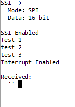
UARTprintf("SSI ->\n");
UARTprintf(" Mode: SPI\n");
UARTprintf(" Data: 16-bit\n\n");
//
// Init SPI2 as slave.
//
UARTprintf("290\n\n");
InitSPI2();
UARTprintf("292\n\n");
//
// Enable RX timeout interrupt.
//
SSIIntEnable(SSI2_BASE, SSI_RXTO);
//
// Read any residual data from the SSI port. This makes sure the receive
// FIFOs are empty, so we don't read any unwanted junk. This is done here
// because the SPI SSI mode is full-duplex, which allows you to send and
// receive at the same time. The SSIDataGetNonBlocking function returns
// "true" when data was returned, and "false" when no data was returned.
// The "non-blocking" function checks if there is any data in the receive
// FIFO and does not "hang" if there isn't.
//
while(SSIDataGetNonBlocking(SSI2_BASE, &g_ulDataRx2[0]))
{
}
//
// Clear any pending interrupt
//
SSIIntClear(SSI2_BASE, SSI_RXTO);
//
//
IntEnable(INT_SSI2);
//
// Wait for the SSI2 RXTO interrupt to fire and data read from RXFIFO.
//
while(g_ulSSI2RXTO == 0)
{
UARTprintf("\waiting...\n ");
}
//
// Display indication that salve has receiving data.
//
UARTprintf("\nReceived:\n ");
//
// Display the 3 bytes of data that were read from RX FIFO.
//
for(ulindex = 0; ulindex < NUM_SSI_DATA; ulindex++)
{
UARTprintf("'%c' ", g_ulDataRx2[ulindex]);
}
if(g_ulSSI2RXTO > 1)
{
//
// Tell the user that the test failed and the reason.
//
UARTprintf("\n\nError: %d interrupt(s) fired when expecting only one."
"\n", g_ulSSI2RXTO);
}
else
{
//
// Tell the user that the test passed.
//
UARTprintf("\n\nTest Passed.\n\n");
}
while(1)
{
}
}
For whatever reason, TI's website will not let me place another code object, so for the arduino:
#include<SPI.h>
void setup() {
// put your setup code here, to run once:
Serial.begin(115200);
SPI.begin();
//SPI.setClockDivider(SPI_CLOCK_DIV8);
digitalWrite(SS,HIGH);
}
void loop() {
// put your main code here, to run repeatedly:
Serial.println("Sending over SPI");
byte master_send, master_receive;
digitalWrite(SS, LOW);
master_send = 1;
master_receive = SPI.transfer(master_send);
if(master_receive == 1) //Logic for setting the LED output depending upon value received from slave
{
Serial.println("SPI working");
}
delay(1000);
}