This thread has been locked.

If you have a related question, please click the "Ask a related question" button in the top right corner. The newly created question will be automatically linked to this question.

TM4C1294KCPDT: ADC -Sample Sequencers

Part Number: TM4C1294KCPDT
Other Parts Discussed in Thread: EK-TM4C1294XL

hi,

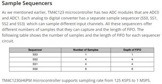
   I am using TM4C1294KCPDT controller . I want to intialised two analog pins , in this i am not aware of ADC Sample Sequencers . Any body can explain this with example?

what its means number of sample and Depth of FIFO ? how i can use this in configuration.

Thanks in advance.

Thanks & Regards,

Rani

  • Part Number: TM4C1294KCPDT

    Hi,

     would like to configure the ADC Sequence number as 3 and Step as 1 in ADCSequenceStepConfigure  . So if  i configure my API like ADCSequenceStepConfigure( ADC0_BASE, 3,3 ADC_CTL_CH8)   is this correct ?

    void ADCSequenceStepConfigure	(	uint32_t 	ui32Base,
    uint32_t 	ui32SequenceNum,
    uint32_t 	ui32Step,
    uint32_t 	ui32Config 
    )	

    If am Choosing   1. Sequencer-3 ,1 step  as   ADCSequenceStepConfigure( ADC0_BASE, 3,3 ADC_CTL_CH8)

                               2. Sequencer-2 ,  4 steps as ADCSequenceStepConfigure( ADC0_BASE, 2,4 ADC_CTL_CH8)

                              3. Sequencer-0 , 8 steps  as ADCSequenceStepConfigure( ADC0_BASE, 0,8 ADC_CTL_CH8)

    Please correct it if i am wrong ...

    Thanks in advance 

    Thanks & Regards,

    Rani 

  • Hello Rani,

    So if  i configure my API like ADCSequenceStepConfigure( ADC0_BASE, 3,3 ADC_CTL_CH8)   is this correct ?

    Not quite. For Sequence 3, Step 1 you would use the following: Edit: See comments on 11/9/2021 for correct configuration.

    ADCSequenceStepConfigure(ADC0_BASE, 3, 1, ADC_CTL_CH8);

    The Sequence number is 3, and the Step number is 1. Edit: See comments on 11/9/2021 for correct configuration.

    For Sequence 2 / Sequence 0, your code is correct. Edit: See comments on 11/9/2021 for correct configuration.

    Any body can explain this with example?

    We have example codes for the ADC in TivaWare - I believe you may have found these on your own already but there is an example for the EK-TM4C1294XL LaunchPad at [Install Path]\TivaWare_C_Series-2.2.0.295\examples\boards\ek-tm4c1294xl\adc_udma_pingpong.

    There also are additional examples at [Install Path]\TivaWare_C_Series-2.2.0.295\examples\peripherals\adc

    what its means number of sample and Depth of FIFO ?

    The number of samples would indicate how many samples are gathered before an interrupt is triggered to indicate that sampling is completed. The FIFO depth indicates the maximum number of samples that can be stored before the FIFO is full. Once the FIFO is full, future writes will not occur until the FIFO is emptied but an overflow flag will be triggered to indicate the ADC was not serviced quick enough and sample data was lost as a result.

    Best Regards,

    Ralph Jacobi

  • Ralph Jacobi ,

        I have seen some example code for ADC , in that they configured like below but i couldnt understand  .Can you explain it.

       ADCSequenceStepConfigure(ADC0_BASE, 0, 0, ADC_CTL_CH0);
       ADCSequenceStepConfigure(ADC0_BASE, 0, 1, (ADC_CTL_CH4));
       ADCSequenceStepConfigure(ADC0_BASE, 0, 2, ADC_CTL_CH8);
       ADCSequenceStepConfigure(ADC0_BASE, 0, 3, (ADC_CTL_CH9 | ADC_CTL_IE | ADC_CTL_END));

    Sequencer-0 means steps should be 8 only i think so .... but here they mentiond variously ... above configurations are correct ?

    Best Regards,

    Rani

  • Hello Rani,

    I have to correct myself slightly here as I wasn't thinking in terms of code conversions properly which is that for the registers, the Steps are 0 through 7 and not 1 through 8. So actually your prior code was not accurate for TivaWare APIs. The correct values would be:

    ADCSequenceStepConfigure(ADC0_BASE, 3, 0, ADC_CTL_CH8 | ADC_CTL_IE | ADC_CTL_END);
    
    ADCSequenceStepConfigure(ADC0_BASE, 2, 3, ADC_CTL_CH8 | ADC_CTL_IE | ADC_CTL_END);
    
    ADCSequenceStepConfigure(ADC0_BASE, 0, 7, ADC_CTL_CH8 | ADC_CTL_IE | ADC_CTL_END);

    I also appended in now the  ADC_CTL_IE | ADC_CTL_END aspect which is used for those final steps because they would be the last sample in the sequence. ADC_CTL_IE is typical to add in so that your interrupts properly are triggered, but that would not be needed if you are using the manual triggers. ADC_CTL_END is important to mark the end of your sampling. 

    Regarding the steps themselves, the step value determines the order in which the samples are captured by the ADC when the trigger occurs. So you can set any value that is eligible for the sequence. Additionally, if you can have multiple steps for a sequence, you can select different channels to be used for each step. For Sequence 0 which has 8 samples available, you can select to sample from up to 8 different inputs before triggering the interrupt.

    What the code you posted is doing that for four inputs where the first sample is done on CH0 for Step 0, the second sample is on CH4 for Step 1, the third on CH8 for Step 2, and the fourth sample is on CH9 which is Step 3 and Step 3 is the last step so the interrupt would trigger after that sample is processed.

    Now the ADC FIFO which is 4 values deep will have the 4 samples in it. As it is a FIFO, reading it out will get the values in the order they were samples which is CH0, CH4, CH8, and CH9.

    If you want to get 8 measurements from a single channel then you would need to configure all 8 steps which means the code would look like this:

    ADCSequenceStepConfigure(ADC_BASE, 0, 0, ADC_CTL_CH1);
    ADCSequenceStepConfigure(ADC_BASE, 0, 1, ADC_CTL_CH1);
    ADCSequenceStepConfigure(ADC_BASE, 0, 2, ADC_CTL_CH1);
    ADCSequenceStepConfigure(ADC_BASE, 0, 3, ADC_CTL_CH1);
    ADCSequenceStepConfigure(ADC_BASE, 0, 4, ADC_CTL_CH1);
    ADCSequenceStepConfigure(ADC_BASE, 0, 5, ADC_CTL_CH1);
    ADCSequenceStepConfigure(ADC_BASE, 0, 6, ADC_CTL_CH1);
    ADCSequenceStepConfigure(ADC_BASE, 0, 7, (ADC_CTL_CH1 | ADC_CTL_END));
    

    I apologize for my lackluster reply previously that did not help your understanding of the sequencers and steps well. I hope this provides a lot clarity about the correct way to configure the ADC peripheral.

    Best Regards,

    Ralph Jacobi