This thread has been locked.

If you have a related question, please click the "Ask a related question" button in the top right corner. The newly created question will be automatically linked to this question.

TMS570LC4357: N2HET : Issue in fetching the encoder signals.

Part Number: TMS570LC4357
Other Parts Discussed in Thread: HALCOGEN

Hello Team,

I was trying to fetch the encoder signals of the motor in my project.
These are the statements I have written for reading the master motor encoder signals :-

capGetSignal(hetRAM2, cap0, &enc_a_master);//enc_b_master /* CAP0 = N2HET2_19 */ /* Working */
capGetSignal(hetRAM2, cap1, &enc_b_master);//enc_a_master /* CAP1 = N2HET2_20 */ /* Not working */

Here the first statement is working properly, but N2HET2_20 is not working.

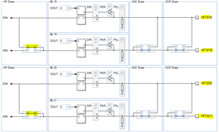
Please refer the below attached screenshot of halcogen configurations for HET2:
Kindly let me know if the configurations are correct or is there any thing missing.

  • Hi,

    Do you use the HalCoGen generated N2HET code? Are the input signals applied to N2HET2[19] and N2HET2[20] terminals?

  • For input signal capture, the N2HET2[n] and N2HET2[n+1] are paired, N2HET2[n] is used to capture the pulse width, and N2HET2[n+1] is to capture the period. The HR SHARE needs to be enabled for pin n and pin n+1. HR structure of pin n is used for pulse width, and HR structure of pin n+1 is to measure the period. 

    In your configuration, the HR SHARE is disabled for pin 19 (pin 18 and pin 19)  and pin 20 (pin 20, and pin 21). But in the generated code, 

    capGetSignal(hetRAM2, cap0, &enc_a_master); --> read the period of input signal at pin 19, and read the pulse width of input signal at pin 18. There is no input at pin 18, so you will get 0% for duty cycle. You will get correct period, but wrong duty cycle.

    capGetSignal(hetRAM2, cap1, &enc_a_master); -->read the period of signal at pin 21, and pulse width of signal at pin 20. Since there is no input at pin 21, you will get wrong duty cycle and wrong period.

    Please enable the HR share, and use the even pin (pin 18, and pin 20) for capture.

  • Hi QJ Wang,

    Thank you for your response.

    Is it necessary to keep N2HET2[18] & N2HET2[21] peripheral pins free for capturing the signals connected to N2HET2[19] & N2HET2[20]?

    The following is our hardware connection,

    We have connected a quadrature encoder A channel to N2HET2[19] in pin P4 & encoder B channel to N2HET2[20] in pin T5.

    Our requirement is to get the number of pulses and period of the encoder signals. We configured in HalCogen as shown in the previous screenshots & as per your suggestion we have enabled the HR share and changed the direction to input.

    In our hardware N2HET2[21] in pin T6 is connected for some other function. Should we keep N2HET2[21] pin open to get the period?


    Will this connection leads to any issues in getting period from N2HET2[21]?


  • Is it necessary to keep N2HET2[18] & N2HET2[21] peripheral pins free for capturing the signals connected to N2HET2[19] & N2HET2[20]?

    The N2HET supports high resolution and low resolution. For HR, the resolution is one period of HR clock, but it is one LRP for low resolution. 

    H2NET has one restriction: for each pin at most one high resolution instruction can be executed per loop resolution period. For example, you want to measure period and duty cycle of the input signal at pin N2HET2[18], and two PCNT instructions are required. One instruction is to measure the period, and another one is to measure the pulse width (rising edge to rising edge, or falling edge to falling edge). Since the restriction, only one PCNT for N2HET2[18} can use the HR feature.

    In order to let the 2nd PCNT uses the HR feature, we can enable the "HR Structure Sharing". The HR structure of N2HET2[18] and HR structure of N2HET2[19] can be used to measure the input signal at pin N2HET2[18]. The input signal has to be at N2HET2[18] (even number). The N2HET2[19] pin can be used as GIO or other functionality, but not N2HET.

    For N2HET2[21], its HR structure can be used by pin N2HET2[20], but N2HET2[21] can not use the HR structure of N2HET2[20]. To measure the input signal at N2HET2[21], only one PCNT can use the HR feature. But the issue is that the HALCOGen generated code assumes the input signal is at the even pin number (18, 20, 22, ..). You have to modify the code for your special use case.

    Is terminal P4 also used for N2HET, or LIN?

    What is your resolution requirements?

  • Hi QJ Wang,

    In P4 we have connected encoder A channel and using N2HET2[19]. In T5 we have connected encoder B channel and using N2HET2[20].

    Encoder B channel(N2HET2[20]) is working properly. The maximum frequency we expect on the encoder channel is approximately 2MHz.

    We are expecting the same accuracy that we are receiving in encoder B channel (N2HET2[20]).

    Request you to support for the modification required in the code for this case.  

  • Hi QJ Wang,

    The resolution we are looking at is, as you mentioned in the above thread, support for modifying the code to read the period from N2HET2[19] pin.

    Requesting your support to modify the code.

  • The HALCOGen generated N2HET code doesn't work for your HW setup. You need to modify the code for your setup.

    1. How many N2HET pins are used in your application? 

    2. Which pins are used to capture input signal? which pins are to output PWM signals? I'd like to estimate how many instructions are needed.

    3. For signal capturing, do you want to calculate the period AND duty-cycle or only period? If only period is needed, you don't need to change your HW. If you want to calculate both period and duty-cycle, and high resolution is required, you need to change your HW. For example, connect ENC_A_M to N2HET2[22], and connect MOT_REL_S_B_A to N2HET2[24].

  • Hi QJ Wang,

    We are looking only for period calculation, duty cycle is not required.

    Below are the hardware connections for N2HET

    (Function - Pin --> Hardware function, Description) 

    N2HET2[18] - N4 --> OPEN RELAY, this pin is used as a digital output to control a relay.

    N2HET2[19] - P4 --> ENCODER A SIGNAL, this pin is used for capturing the period from ENCODER A SIGNAL.

    N2HET2[20] - T5 --> ENCODER B SIGNAL, this pin is used for capturing the period from ENCODER B SIGNAL.

    N2HET2[21] - T6 --> OPEN RELAY, this pin is used as a digital output to control a relay.

    PWM Generation hardware connections

    (Function - Pin --> Hardware function, Description)

    EPWM1A - D9   --> LIN1, Low side logic input-1 for motor driver.

    EPWM1B - D10 --> HIN1, High side logic input-1 for motor driver.

    EPWM2A - M1   --> LIN2, Low side logic input-2 for motor driver.

    EPWM2B - K18 --> HIN2, High side logic input-2 for motor driver.

    EPWM3A - W5  --> LIN3, Low side logic input-3 for motor driver.

    EPWM3B - V6   --> HIN3, High side logic input-3 for motor driver.

    Kindly request you to support for the changes required in driver level code for calculating period for ENCODER SIGNALS connected in N2HET2[19] & N2HET2[20], as per the above hardware connections.

  • Hi Aswin,

    How are the waveform of the output signal at N2HET2[18] and N2HET2[21]? You can configure those two pins as GIO pins to control the relays.

    The following code can be used to capture the signals at N2HET2[19] and N2HET2[20]:

    ; Input Period measurements with PCNT
    ; Clear HRSHARE register bit 9; Measure RISE2RISE from input signal on pin 19
    ; Clear HRSHARE register bit 10; Measure RISE2RISE from input signal on pin 20

    L00 PCNT { type=RISE2RISE, pin=19};
    L01 PCNT { type=RISE2RISE, pin=20};
    L04 BR { next=L00,cond_addr=L00,event=NOCOND};

    Please use HET IDE to debug the code.

  • Hi QJ Wang,

    N2HET2[18] and N2HET2[21] are digital output pins and are controlled in due course of code.

    Thanks for the changes required in the driver level code for capturing signals at pin 19 & 20.

    We are working on the implementation based on your input, and will update you the status.

    Thanking you for the support.

  • Hi QJ Wang,

    QJ: How are the waveform of the output signal at N2HET2[18] and N2HET2[21]? 

    We connected and en route in the hardware for encoder channel A from N2HET2[19] to N2HET2[18] as input and configured as HR share.

    And the old trace in PCB for ENC_A_M to N2HET2[19] MCU pin is lift up and no connection to MCU.

    But still we facing voltage drop 3.3V to 1.1V for the connection ENC_A_M to N2HET2[18] MCU pin. There is no consistent signal of 3.3V for encoder A channel.

    Voltage drop tested few scenarios:

    1. 3.3V ok -> Without MCU when measuring encoder signals coming from base board through connector to MCU the encoder A signal is ok to 3.3V.

    2. 3.3V ok -> With MCU and erase entire flash memory and no firmware the measuring signals are ok to 3.3V.

    3. 3.3V Not ok -> with MCU and configure ENC_A_M to N2HET2[18] MCU pin(as input) and HR share enabled to N2HET2[19] pin(as output). observed a voltage drop 3.3V to 1.1V.

    What does this cause voltage drop for encoder signal? 

    Kindly advise.

    Thanks for your support.

  • Hi QJ,

    Any update on this?

  • Hi Haribabu,

    3. 3.3V Not ok -> with MCU and configure ENC_A_M to N2HET2[18] MCU pin(as input) and HR share enabled to N2HET2[19] pin(as output). observed a voltage drop 3.3V to 1.1V.

    What is the voltage level if the HR share is disabled? If HR share is enabled, only of the two pins can be used as N2HET pins. Can you disable the internal pull-down if it is enabled?

  • Hi QJ,

    Enable HR share With Pull down -> Voltage drop in N2HET18

    Enable HR share With Pull Up -> Voltage drop in N2HET18

    Disable HR share without pull up/down-> Voltage drop in N2HET18

    Enable HR share no pull up/down -> Voltage drop in N2HET 18


    But without MCU/FW there is no voltage drop in the signal line.

    Kindly advice.

    Thanks