This thread has been locked.

If you have a related question, please click the "Ask a related question" button in the top right corner. The newly created question will be automatically linked to this question.

TMS570LC4357-EP: ADC 1 module failure

Part Number: TMS570LC4357-EP

Hello,

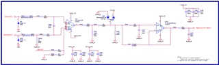
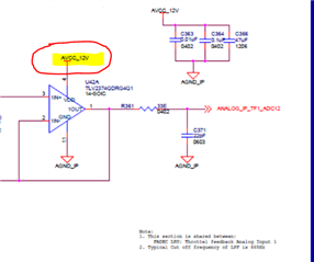
We are reading incorrect values on all channels of ADC1 module. The input voltage given is 1.27V but the value read is 1.66V in ADC1 module.

But ADC2 module is working properly and the values are read correctly.

In case of shared channels, ADC1 channel reading is wrong and ADC2 reading is correct.

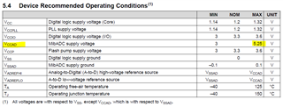
Both ADC modules are configured in 12bit resolution mode.

Earlier, the readings on both ADC modules were correct, & now there is failure on ADC1 module channels only.

Can you please let us know what could be the root cause of this failure.

Thank you..

  • Hi,

    Earlier, the readings on both ADC modules were correct, & now there is failure on ADC1 module channels only.

      Is this your custom board or the TI EVM/LaunchPad board?

      Do you either have another custom board or launchPad to try? I want to know if this a board level issue.

      How are you connecting the input to ADC1? Is it from a sensor on the board or off board?

      Did you ever supply higher voltage input to ADC1 that can potentially damage the chip?

      Are you going through some voltage divider before the input?


  • Hello,

    Thanks for the response.

    The ADC1 module failure occurred in the custom board.

    We have another custom board and ADC1 module works fine there.

    We have the conditioning circuit before ADC inputs and No high voltage input was given.

    Attached snapshot of the conditioning circuit.

    Also, the controller seems to be completely damaged as we are not able to load code using JTAG.

  • HI,

    The ADC1 module failure occurred in the custom board.

    We have another custom board and ADC1 module works fine there.

    I think the MCU is probably damaged due to EOS (Electrical Overstress). Looking at your schematic, it seems that your Oa-amp operates at 12V. Is this correct? I also don't see a voltage divider before ADC input. This means the input and output of the op-amp can go from rail-to-rail. Is this correct? Please note MCU's maximum VCCAD voltage is 5.25. You cannot exceed this voltage. 

    Check if your op-amp can be operated with same input supply as that of the ADC. This configuration ensures that the input to ADC will never go beyond the ADC supply range since the operational amplifier will get saturated when the output gets close to supply rails, thus protecting the ADC inputs. This is the simplest way of protecting the inputs. Please reference below app note. 

    https://www.ti.com/lit/slaa593