This thread has been locked.

If you have a related question, please click the "Ask a related question" button in the top right corner. The newly created question will be automatically linked to this question.

TMS570LS0914 ADC converter stucks

Other Parts Discussed in Thread: INA828, TMS570LS0914, HALCOGEN

Hi all,

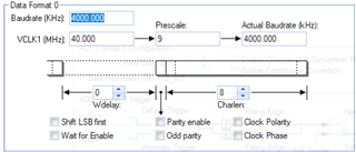
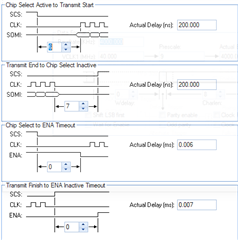
I use a INA828 chip (Precision Instrumentation Amplifier, also from TI ) with offset of 2.5V and a microcontroller TMS570LS0914 as a data logger. I store the received ADC data via SPI on a SD card.

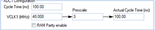
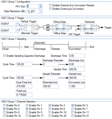
The ADC converter is starting every 100us via rti interrupt. My test signal is a 1kHz test signal. So I have an oversampling of 10 times.

If I log the data it seems that the ADC converter stucks periodically.

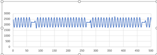
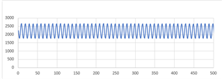
But it is absolute crazy if I use an oscilloscope to see if the input data are correct it is working fine.

Any ideas where I have to look ?

Best regards

Lars

  • Hi Lars,

    How do you read the ADC conversion results? What are the settings of the ADC and SPI transfer?

    Is the first picture from the logger data in SD card, or the original data from the ADC conversion memory?

  • Hi,

    I used a 100us RTI interrupts and in this interrupt routine I implemend the following line of code:   

    adcStartConversion(adcREG1,adcGROUP1);
    while(!adcIsConversionComplete(adcREG1, adcGROUP1));
    ulAdcStatus = adcGetData(adcREG1, adcGROUP1, &adc1_data[0]);

    I store the ADC data in a double buffer. In a second RTI interrupt routine 12.8ms (128 values) the data of one buffer are send via SPI to the SD card. The second buffer is filled up with the new ADC data. I also used the "reentrant_irq.h", so that the 100us RTI task can interrupt the 12.8ms task.

    So I used the following ADC settings:

    My SPI Settings are:

    So I think I used normal settings nothing special.

    Best regards

    Lars

  • So one more information about your question:

    Is the first picture from the logger data in SD card, or the original data from the ADC conversion memory?

    Both picures are showing the data logged via the ADC converter and stored on the SD card.

    The first picture includes the values measured by the ADC and stored on the SD card. But without using an osciloscope.

    The second picture includes the values measured by the ADC and stored on the SD card. But I used an osciloscope to verify if my input data are really correct. And that's what I do not understand. If I use the osciloscope everythink is ok and it is working fine. And if I do not use the osciloscope it seems that the ADC converter stucks. And it seems that is stucks periodically but not in the 12.8ms task. It is about 20ms. But I do not have any 20ms task.

    Best regards

    Lars

  • Hi Lar,

    I also used the "reentrant_irq.h", so that the 100us RTI task can interrupt the 12.8ms task.

    Do you use the nexted interrupt that the IRQ is re-enabled in your 2nd RTI (12.8ms) ISR? Normally the IRQ is disabled in the interrupt ISR, so another interrupt has to wait until the current ISR has finished. 

    Did you measure the time took by end RTI ISR using PMU? I think it might take more than 10ms if you use the HALCoGen generated API: spiTransmitData(). From the picture 1, around 12~15 ADC data are missed.

    Can you use multi-buffered SPI instead of compatible SPI? MibSPI1 TG0 can support up to 256 buffers. In 2nd RTI ISR, you only need to copy the 128 data from buffer one to MibSPI SRAM using either CPU or DMA, and trigger MibSPI transfer.  Uisng this way, the 2nd RTI may take less than 1ms.