This thread has been locked.

If you have a related question, please click the "Ask a related question" button in the top right corner. The newly created question will be automatically linked to this question.

TM4C1230D5PM: SysConfig TM4C1230D5PM configuration from CCS11

Part Number: TM4C1230D5PM
Other Parts Discussed in Thread: SYSCONFIG,

Hi,

Long time I don't use CCS and TI's microprocessors. Sorry!

Due to the global supply problem, I think that the use of TM4C123x devices can be (at the moment) a good alternative for my project. Lately I'm used to using IDEs from other firms such as ST, NXP, Silabs, Microchip... and these include some utilities like Pinmux configuration to easily configure the system clock, GPIOs, etc

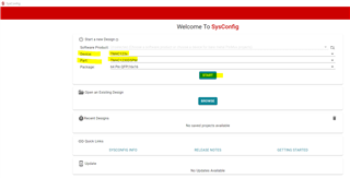
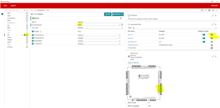
Where's this utility in CCS11? It seems there's something called SysConfig but I am not able to create a project (i.e. a blink example) with this option.

Could anyone help me with this?

regards,
gaston

  • Hi,

      Please refer to the below link for SysConfig download. 

    https://www.ti.com/tool/SYSCONFIG

      I will suggest you first download TivaWare if you have not done so. TivaWare is a software development kit which include a suite of software libraries for s/w development. There are many examples you can reference as a baseline for your projects. 

    https://www.ti.com/tool/download/SW-TM4C

  • It seems that TivaWare is intended for using on Windows OS (.exe files). Any alternative for Linux distributions?

    gaston

  • Hi,

    I've downloaded TivaWare software package and installed it successfully using wine. Then I've installed SysConfig too and imported the blinky example project. It compile as expected.

    However I still don't know how to configure the pinmux of the TM4C1230D5PM device using the SysConfig tool.

    regards,
    gaston

  • HI,

    I hardly use this tool when creating applications for TM4C MCU. I suppose you can bring up the tool like below, correct? I select TM4C1230D5PM as the device and then hit "Start". 

    Let's suppose I want to use the SSI0 module on this device, I first select SSI on the left pane and then select SSI0 as the module instance. There are four SSI modules on this device so you need to specify which one you want to use. On the lower right, it will show you what pins are used for SSI0. On the upper right, you can click the "Save" icon to save the pinout.c and pinout.h files that you can include into your project. 

    Below is the pinout.h and pinout.c examples. As you can see you just need to call PinoutSet() function that will configure pins for use as SSI functions. It is just a convenient way to let the tool configure the pins for you. However, I seldom find people use the pinmux tool including myself. Normally, I will just write the code myself to configure the pins. I guess I'm not taking advantage of the tool provided. 

    //*****************************************************************************
    
    // This file was automatically generated on 11/29/2021 at 9:23:13 AM
    // by TI PinMux version 1.8.0+1863
    //
    //*****************************************************************************
    
    #ifndef __DRIVERS_PINOUT_H__
    #define __DRIVERS_PINOUT_H__
    
    //*****************************************************************************
    //
    // If building with a C++ compiler, make all of the definitions in this header
    // have a C binding.
    //
    //*****************************************************************************
    #ifdef __cplusplus
    extern "C"
    {
    #endif
    
    //*****************************************************************************
    //
    // Prototypes.
    //
    //*****************************************************************************
    extern void PinoutSet(void);
    
    //*****************************************************************************
    //
    // Mark the end of the C bindings section for C++ compilers.
    //
    //*****************************************************************************
    #ifdef __cplusplus
    }
    #endif
    
    #endif // __DRIVERS_PINOUT_H__

    // This file was automatically generated on 11/29/2021 at 9:23:09 AM
    // by TI PinMux version 1.8.0+1863
    //
    //*****************************************************************************
    
    #include <stdbool.h>
    #include <stdint.h>
    #include "inc/hw_gpio.h"
    #include "inc/hw_memmap.h"
    #include "inc/hw_types.h"
    #include "driverlib/gpio.h"
    #include "driverlib/pin_map.h"
    #include "driverlib/rom.h"
    #include "driverlib/rom_map.h"
    #include "driverlib/sysctl.h"
    #include "pinout.h"
    
    //*****************************************************************************
    //
    //! \addtogroup pinout_api
    //! @{
    //
    //*****************************************************************************
    
    //*****************************************************************************
    //
    //! Configures the device pins for the customer specific usage.
    //!
    //! \return None.
    //
    //*****************************************************************************
    void
    PinoutSet(void)
    {
        //
        // Enable Peripheral Clocks 
        //
    	MAP_SysCtlPeripheralEnable(SYSCTL_PERIPH_GPIOA);
    
        //
        // Configure the GPIO Pin Mux for PA4
    	// for SSI0RX
        //
    	MAP_GPIOPinConfigure(GPIO_PA4_SSI0RX);
    	MAP_GPIOPinTypeSSI(GPIO_PORTA_BASE, GPIO_PIN_4);
    
        //
        // Configure the GPIO Pin Mux for PA3
    	// for SSI0FSS
        //
    	MAP_GPIOPinConfigure(GPIO_PA3_SSI0FSS);
    	MAP_GPIOPinTypeSSI(GPIO_PORTA_BASE, GPIO_PIN_3);
    
        //
        // Configure the GPIO Pin Mux for PA5
    	// for SSI0TX
        //
    	MAP_GPIOPinConfigure(GPIO_PA5_SSI0TX);
    	MAP_GPIOPinTypeSSI(GPIO_PORTA_BASE, GPIO_PIN_5);
    
        //
        // Configure the GPIO Pin Mux for PA2
    	// for SSI0CLK
        //
    	MAP_GPIOPinConfigure(GPIO_PA2_SSI0CLK);
    	MAP_GPIOPinTypeSSI(GPIO_PORTA_BASE, GPIO_PIN_2);
    
    }
    
    //*****************************************************************************
    //
    // Close the Doxygen group.
    //! @}
    //
    //*****************************************************************************