This thread has been locked.

If you have a related question, please click the "Ask a related question" button in the top right corner. The newly created question will be automatically linked to this question.

TMS570LC4357: TMS570LC4357: HAL Code Generator example_mibspiDMA extended to 4 mibSPIs with 1 transfer group each (cycle time for first cycle differs from all following cycles)

Part Number: TMS570LC4357
Other Parts Discussed in Thread: HALCOGEN,

Measuring the cycle time from start to end of DMA transfer for all mibSPIs shows 1,8 ms. Measuring the cycle time for further cycles from start to end of DMA transfer shows 3,0 ms. Please see the code below. After initialisation phase the code enters an while(1) loop. Within this loop all 4 mibSPs are started sequently taking the HBC Flag into account. At the beginning a PWM Signal is set to 100 % duty and after all DMA channels have completed the transmission the PWM Signal is set to 1 % duty. The 100 % duty is measured with a Digital Storage Oscilloscope. For the first while loop cycle 1,8 ms can be measured. But for all following while loop cycles 3,0 ms are measured. Any idea why there is such a difference?

/* USER CODE BEGIN (0) */
/* USER CODE END */

/* Include Files */

#include "HL_sys_common.h"

/* USER CODE BEGIN (1) */
#include "HL_mibspi.h"
#include "HL_sys_dma.h"
#include "HL_het.h"
#include "HL_reg_het.h"

/* example data Pattern configuration */
#define D_SIZE      128
#define BUFFER_SIZE 1024

void loadDataPattern(uint32 psize, uint16* pptr);
void mibspiEnableInternalLoopback(mibspiBASE_t *mibspi);
void dmaConfigCtrlPacket(uint32 sadd,uint32 dadd,uint32 dsize);
void mibspiDmaConfig(mibspiBASE_t *mibspi,uint32 channel, uint32 txchannel, uint32 rxchannel);

#pragma SET_DATA_SECTION(".sharedRAM")
uint16 TXDATA[BUFFER_SIZE];         /* transmit buffer in sys ram */
uint16 RXDATA[BUFFER_SIZE]= {0};    /* receive  buffer in sys ram */
uint16 TXDATA2[BUFFER_SIZE];         /* transmit buffer in sys ram */
uint16 RXDATA2[BUFFER_SIZE]= {0};    /* receive  buffer in sys ram */
uint16 TXDATA3[BUFFER_SIZE];         /* transmit buffer in sys ram */
uint16 RXDATA3[BUFFER_SIZE]= {0};    /* receive  buffer in sys ram */
uint16 TXDATA4[BUFFER_SIZE];         /* transmit buffer in sys ram */
uint16 RXDATA4[BUFFER_SIZE]= {0};    /* receive  buffer in sys ram */
#pragma SET_DATA_SECTION()

static g_dmaCTRL g_dmaCTRLPKT1, g_dmaCTRLPKT2;    /* dma control packet configuration stack */


/* USER CODE END */

/** @fn void main(void)
*   @brief Application main function
*   @note This function is empty by default.
*
*   This function is called after startup.
*   The user can use this function to implement the application.
*/

/* USER CODE BEGIN (2) */
/* USER CODE END */

void main(void)
{
/* USER CODE BEGIN (3) */

   uint32 i;
   uint32 j;
   uint32 m;

   /* - creating a data chunk in system ram to start with ... */
   loadDataPattern(BUFFER_SIZE,&TXDATA[0]);
   loadDataPattern(BUFFER_SIZE,&TXDATA2[0]);
   loadDataPattern(BUFFER_SIZE,&TXDATA3[0]);
   loadDataPattern(BUFFER_SIZE,&TXDATA4[0]);

   clearDataPattern(BUFFER_SIZE,&RXDATA[0]);
   clearDataPattern(BUFFER_SIZE,&RXDATA2[0]);
   clearDataPattern(BUFFER_SIZE,&RXDATA3[0]);
   clearDataPattern(BUFFER_SIZE,&RXDATA4[0]);

   /* - initializing mibspi - enabling tg 0 , length 127 (halcogen file)*/
   mibspiInit();

   /* - enabling loopback ( this is to emulate data transfer without external wires */
   mibspiEnableInternalLoopback(mibspiREG1);
   mibspiEnableInternalLoopback(mibspiREG2);
   mibspiEnableInternalLoopback(mibspiREG3);
   mibspiEnableInternalLoopback(mibspiREG4);

   /* - configuring dma control packets   */
   g_dmaCTRLPKT1.SADD      = (uint32)TXDATA;    /* source address             */
   g_dmaCTRLPKT1.DADD      = (uint32)&(mibspiRAM1->tx[0].data);    /* destination  address       */
   g_dmaCTRLPKT1.CHCTRL    = 0;                 /* channel control            */
   g_dmaCTRLPKT1.FRCNT	   = 8;//1;                 /* frame count                */
   g_dmaCTRLPKT1.ELCNT     = 32;//D_SIZE;            /* element count              */
   g_dmaCTRLPKT1.ELDOFFSET = 4;                 /* element destination offset */
   g_dmaCTRLPKT1.ELSOFFSET = 0;		            /* element destination offset */
   g_dmaCTRLPKT1.FRDOFFSET = 0;		            /* frame destination offset   */
   g_dmaCTRLPKT1.FRSOFFSET = 0;                 /* frame destination offset   */
   g_dmaCTRLPKT1.PORTASGN  = PORTA_READ_PORTB_WRITE;
   g_dmaCTRLPKT1.RDSIZE    = ACCESS_64_BIT;	    /* read size                  */
   g_dmaCTRLPKT1.WRSIZE    = ACCESS_16_BIT; 	/* write size                 */
   g_dmaCTRLPKT1.TTYPE     = FRAME_TRANSFER ;   /* transfer type              */
   g_dmaCTRLPKT1.ADDMODERD = ADDR_INC1;         /* address mode read          */
   g_dmaCTRLPKT1.ADDMODEWR = ADDR_OFFSET;       /* address mode write         */
   g_dmaCTRLPKT1.AUTOINIT  = AUTOINIT_ON;       /* autoinit                   */

   g_dmaCTRLPKT2.SADD      = (uint32)&(mibspiRAM1->rx[0].data);    /* source address             */
   g_dmaCTRLPKT2.DADD      = (uint32)RXDATA;    /* destination  address       */
   g_dmaCTRLPKT2.CHCTRL    = 0;                 /* channel control            */
   g_dmaCTRLPKT2.FRCNT	   = 8;//1;                 /* frame count                */
   g_dmaCTRLPKT2.ELCNT     = D_SIZE;             /* element count              */
   g_dmaCTRLPKT2.ELDOFFSET = 0;                 /* element destination offset */
   g_dmaCTRLPKT2.ELSOFFSET = 4;		            /* element destination offset */
   g_dmaCTRLPKT2.FRDOFFSET = 0;		            /* frame destination offset   */
   g_dmaCTRLPKT2.FRSOFFSET = 0;                 /* frame destination offset   */
   g_dmaCTRLPKT2.PORTASGN  = PORTB_READ_PORTA_WRITE;
   g_dmaCTRLPKT2.RDSIZE    = ACCESS_16_BIT;	    /* read size                  */
   g_dmaCTRLPKT2.WRSIZE    = ACCESS_64_BIT; 	/* write size                 */
   g_dmaCTRLPKT2.TTYPE     = FRAME_TRANSFER ;   /* transfer type              */
   g_dmaCTRLPKT2.ADDMODERD = ADDR_OFFSET;         /* address mode read          */
   g_dmaCTRLPKT2.ADDMODEWR = ADDR_INC1;       /* address mode write         */
   g_dmaCTRLPKT2.AUTOINIT  = AUTOINIT_ON;       /* autoinit                   */

   /* upto 32 control packets are supported. */

   /* - setting dma control packets */
   dmaSetCtrlPacket(DMA_CH0,g_dmaCTRLPKT2);
   dmaSetCtrlPacket(DMA_CH1,g_dmaCTRLPKT1);

   /* - setting the dma channel to trigger on h/w request */
   dmaSetChEnable(DMA_CH0, DMA_HW);
   dmaSetChEnable(DMA_CH1, DMA_HW);

   /* - configuring dma control packets   */
   g_dmaCTRLPKT1.SADD      = (uint32)TXDATA2;    /* source address             */
   g_dmaCTRLPKT1.DADD      = (uint32)&(mibspiRAM2->tx[0].data);    /* destination  address       */
   g_dmaCTRLPKT1.CHCTRL    = 0;                 /* channel control            */
   g_dmaCTRLPKT1.FRCNT     = 8;//1;                 /* frame count                */
   g_dmaCTRLPKT1.ELCNT     = 32;//D_SIZE;            /* element count              */
   g_dmaCTRLPKT1.ELDOFFSET = 4;                 /* element destination offset */
   g_dmaCTRLPKT1.ELSOFFSET = 0;                 /* element destination offset */
   g_dmaCTRLPKT1.FRDOFFSET = 0;                 /* frame destination offset   */
   g_dmaCTRLPKT1.FRSOFFSET = 0;                 /* frame destination offset   */
   g_dmaCTRLPKT1.PORTASGN  = PORTA_READ_PORTB_WRITE;
   g_dmaCTRLPKT1.RDSIZE    = ACCESS_64_BIT;     /* read size                  */
   g_dmaCTRLPKT1.WRSIZE    = ACCESS_16_BIT;     /* write size                 */
   g_dmaCTRLPKT1.TTYPE     = FRAME_TRANSFER ;   /* transfer type              */
   g_dmaCTRLPKT1.ADDMODERD = ADDR_INC1;         /* address mode read          */
   g_dmaCTRLPKT1.ADDMODEWR = ADDR_OFFSET;       /* address mode write         */
   g_dmaCTRLPKT1.AUTOINIT  = AUTOINIT_ON;       /* autoinit                   */

   g_dmaCTRLPKT2.SADD      = (uint32)&(mibspiRAM2->rx[0].data);    /* source address             */
   g_dmaCTRLPKT2.DADD      = (uint32)RXDATA2;    /* destination  address       */
   g_dmaCTRLPKT2.CHCTRL    = 0;                 /* channel control            */
   g_dmaCTRLPKT2.FRCNT     = 8;//1;                 /* frame count                */
   g_dmaCTRLPKT2.ELCNT     = D_SIZE;             /* element count              */
   g_dmaCTRLPKT2.ELDOFFSET = 0;                 /* element destination offset */
   g_dmaCTRLPKT2.ELSOFFSET = 4;                 /* element destination offset */
   g_dmaCTRLPKT2.FRDOFFSET = 0;                 /* frame destination offset   */
   g_dmaCTRLPKT2.FRSOFFSET = 0;                 /* frame destination offset   */
   g_dmaCTRLPKT2.PORTASGN  = PORTB_READ_PORTA_WRITE;
   g_dmaCTRLPKT2.RDSIZE    = ACCESS_16_BIT;     /* read size                  */
   g_dmaCTRLPKT2.WRSIZE    = ACCESS_64_BIT;     /* write size                 */
   g_dmaCTRLPKT2.TTYPE     = FRAME_TRANSFER ;   /* transfer type              */
   g_dmaCTRLPKT2.ADDMODERD = ADDR_OFFSET;         /* address mode read          */
   g_dmaCTRLPKT2.ADDMODEWR = ADDR_INC1;       /* address mode write         */
   g_dmaCTRLPKT2.AUTOINIT  = AUTOINIT_ON;       /* autoinit                   */

   /* upto 32 control packets are supported. */

   /* - setting dma control packets */
   dmaSetCtrlPacket(DMA_CH2,g_dmaCTRLPKT2);
   dmaSetCtrlPacket(DMA_CH3,g_dmaCTRLPKT1);

   /* - setting the dma channel to trigger on h/w request */
   dmaSetChEnable(DMA_CH2, DMA_HW);
   dmaSetChEnable(DMA_CH3, DMA_HW);

   /* - configuring dma control packets   */
   g_dmaCTRLPKT1.SADD      = (uint32)TXDATA3;    /* source address             */
   g_dmaCTRLPKT1.DADD      = (uint32)&(mibspiRAM3->tx[0].data);    /* destination  address       */
   g_dmaCTRLPKT1.CHCTRL    = 0;                 /* channel control            */
   g_dmaCTRLPKT1.FRCNT     = 8;//1;                 /* frame count                */
   g_dmaCTRLPKT1.ELCNT     = 32;//D_SIZE;            /* element count              */
   g_dmaCTRLPKT1.ELDOFFSET = 4;                 /* element destination offset */
   g_dmaCTRLPKT1.ELSOFFSET = 0;                 /* element destination offset */
   g_dmaCTRLPKT1.FRDOFFSET = 0;                 /* frame destination offset   */
   g_dmaCTRLPKT1.FRSOFFSET = 0;                 /* frame destination offset   */
   g_dmaCTRLPKT1.PORTASGN  = PORTA_READ_PORTB_WRITE;
   g_dmaCTRLPKT1.RDSIZE    = ACCESS_64_BIT;     /* read size                  */
   g_dmaCTRLPKT1.WRSIZE    = ACCESS_16_BIT;     /* write size                 */
   g_dmaCTRLPKT1.TTYPE     = FRAME_TRANSFER ;   /* transfer type              */
   g_dmaCTRLPKT1.ADDMODERD = ADDR_INC1;         /* address mode read          */
   g_dmaCTRLPKT1.ADDMODEWR = ADDR_OFFSET;       /* address mode write         */
   g_dmaCTRLPKT1.AUTOINIT  = AUTOINIT_ON;       /* autoinit                   */

   g_dmaCTRLPKT2.SADD      = (uint32)&(mibspiRAM3->rx[0].data);    /* source address             */
   g_dmaCTRLPKT2.DADD      = (uint32)RXDATA3;    /* destination  address       */
   g_dmaCTRLPKT2.CHCTRL    = 0;                 /* channel control            */
   g_dmaCTRLPKT2.FRCNT     = 8;//1;                 /* frame count                */
   g_dmaCTRLPKT2.ELCNT     = D_SIZE;             /* element count              */
   g_dmaCTRLPKT2.ELDOFFSET = 0;                 /* element destination offset */
   g_dmaCTRLPKT2.ELSOFFSET = 4;                 /* element destination offset */
   g_dmaCTRLPKT2.FRDOFFSET = 0;                 /* frame destination offset   */
   g_dmaCTRLPKT2.FRSOFFSET = 0;                 /* frame destination offset   */
   g_dmaCTRLPKT2.PORTASGN  = PORTB_READ_PORTA_WRITE;
   g_dmaCTRLPKT2.RDSIZE    = ACCESS_16_BIT;     /* read size                  */
   g_dmaCTRLPKT2.WRSIZE    = ACCESS_64_BIT;     /* write size                 */
   g_dmaCTRLPKT2.TTYPE     = FRAME_TRANSFER ;   /* transfer type              */
   g_dmaCTRLPKT2.ADDMODERD = ADDR_OFFSET;         /* address mode read          */
   g_dmaCTRLPKT2.ADDMODEWR = ADDR_INC1;       /* address mode write         */
   g_dmaCTRLPKT2.AUTOINIT  = AUTOINIT_ON;       /* autoinit                   */

   /* upto 32 control packets are supported. */

   /* - setting dma control packets */
   dmaSetCtrlPacket(DMA_CH4,g_dmaCTRLPKT2);
   dmaSetCtrlPacket(DMA_CH5,g_dmaCTRLPKT1);

   dmaReqAssign(DMA_CH4, DMA_REQ14);
   dmaReqAssign(DMA_CH5, DMA_REQ15);

   /* - setting the dma channel to trigger on h/w request */
   dmaSetChEnable(DMA_CH4, DMA_HW);
   dmaSetChEnable(DMA_CH5, DMA_HW);

   /* - configuring dma control packets   */
   g_dmaCTRLPKT1.SADD      = (uint32)TXDATA4;    /* source address             */
   g_dmaCTRLPKT1.DADD      = (uint32)&(mibspiRAM4->tx[0].data);    /* destination  address       */
   g_dmaCTRLPKT1.CHCTRL    = 0;                 /* channel control            */
   g_dmaCTRLPKT1.FRCNT     = 8;//1;                 /* frame count                */
   g_dmaCTRLPKT1.ELCNT     = 32;//D_SIZE;            /* element count              */
   g_dmaCTRLPKT1.ELDOFFSET = 4;                 /* element destination offset */
   g_dmaCTRLPKT1.ELSOFFSET = 0;                 /* element destination offset */
   g_dmaCTRLPKT1.FRDOFFSET = 0;                 /* frame destination offset   */
   g_dmaCTRLPKT1.FRSOFFSET = 0;                 /* frame destination offset   */
   g_dmaCTRLPKT1.PORTASGN  = PORTA_READ_PORTB_WRITE;
   g_dmaCTRLPKT1.RDSIZE    = ACCESS_64_BIT;     /* read size                  */
   g_dmaCTRLPKT1.WRSIZE    = ACCESS_16_BIT;     /* write size                 */
   g_dmaCTRLPKT1.TTYPE     = FRAME_TRANSFER ;   /* transfer type              */
   g_dmaCTRLPKT1.ADDMODERD = ADDR_INC1;         /* address mode read          */
   g_dmaCTRLPKT1.ADDMODEWR = ADDR_OFFSET;       /* address mode write         */
   g_dmaCTRLPKT1.AUTOINIT  = AUTOINIT_ON;       /* autoinit                   */

   g_dmaCTRLPKT2.SADD      = (uint32)&(mibspiRAM4->rx[0].data);    /* source address             */
   g_dmaCTRLPKT2.DADD      = (uint32)RXDATA4;    /* destination  address       */
   g_dmaCTRLPKT2.CHCTRL    = 0;                 /* channel control            */
   g_dmaCTRLPKT2.FRCNT     = 8;//1;                 /* frame count                */
   g_dmaCTRLPKT2.ELCNT     = D_SIZE;             /* element count              */
   g_dmaCTRLPKT2.ELDOFFSET = 0;                 /* element destination offset */
   g_dmaCTRLPKT2.ELSOFFSET = 4;                 /* element destination offset */
   g_dmaCTRLPKT2.FRDOFFSET = 0;                 /* frame destination offset   */
   g_dmaCTRLPKT2.FRSOFFSET = 0;                 /* frame destination offset   */
   g_dmaCTRLPKT2.PORTASGN  = PORTB_READ_PORTA_WRITE;
   g_dmaCTRLPKT2.RDSIZE    = ACCESS_16_BIT;     /* read size                  */
   g_dmaCTRLPKT2.WRSIZE    = ACCESS_64_BIT;     /* write size                 */
   g_dmaCTRLPKT2.TTYPE     = FRAME_TRANSFER ;   /* transfer type              */
   g_dmaCTRLPKT2.ADDMODERD = ADDR_OFFSET;         /* address mode read          */
   g_dmaCTRLPKT2.ADDMODEWR = ADDR_INC1;       /* address mode write         */
   g_dmaCTRLPKT2.AUTOINIT  = AUTOINIT_ON;       /* autoinit                   */

   /* upto 32 control packets are supported. */

   /* - setting dma control packets */
   dmaSetCtrlPacket(DMA_CH6,g_dmaCTRLPKT2);
   dmaSetCtrlPacket(DMA_CH7,g_dmaCTRLPKT1);

   dmaReqAssign(DMA_CH6, DMA_REQ24);
   dmaReqAssign(DMA_CH7, DMA_REQ25);

   /* - setting the dma channel to trigger on h/w request */
   dmaSetChEnable(DMA_CH6, DMA_HW);
   dmaSetChEnable(DMA_CH7, DMA_HW);

   //dmaReqAssign(DMA_CH0, DMA_REQ0);
   //dmaReqAssign(DMA_CH1, DMA_REQ1);

   /* - configuring the mibspi dma , channel 0 , tx line -0 , rxline -1     */
   /* - refer to the device data sheet dma request source for mibspi tx/rx  */
   mibspiDmaConfig(mibspiREG1,0,0,1);
   mibspiDmaConfig(mibspiREG2,0,0,1);
   mibspiDmaConfig(mibspiREG3,0,0,1);
   mibspiDmaConfig(mibspiREG4,0,0,1);

   dmaEnable();
   hetInit();
   pwmSetDuty(hetRAM1, 0, 1);

   i = 0;

while(1)
{
   i++;

   pwmSetDuty(hetRAM1, 0, 100);

   /* - start the mibspi transfer tg 0 */
   mibspiTransfer(mibspiREG1,0 );

   while(dmaGetInterruptStatus(DMA_CH0, HBC) == FALSE);

   mibspiTransfer(mibspiREG2,0 );

   //while(dmaGetInterruptStatus(DMA_CH0, BTC) == FALSE);
   while(dmaGetInterruptStatus(DMA_CH2, HBC) == FALSE);

   mibspiTransfer(mibspiREG3,0 );

   while(dmaGetInterruptStatus(DMA_CH4, HBC) == FALSE);

   mibspiTransfer(mibspiREG4,0 );

   while(dmaGetInterruptStatus(DMA_CH6, BTC) == FALSE);

   //while(dmaGetInterruptStatus(DMA_CH6, BTC) == FALSE);
   //while(dmaGetInterruptStatus(DMA_CH0, BTC) == FALSE);
   //while(dmaGetInterruptStatus(DMA_CH2, BTC) == FALSE);
   //while(dmaGetInterruptStatus(DMA_CH4, BTC) == FALSE);

   pwmSetDuty(hetRAM1, 0, 1);

   mibspiDisableTransfer(mibspiREG1,0);
   mibspiDisableTransfer(mibspiREG2,0);
   mibspiDisableTransfer(mibspiREG3,0);
   mibspiDisableTransfer(mibspiREG4,0);

   dmaREG->BTCFLAG = 0xFFFFFFFF;
   dmaREG->HBCFLAG = 0xFFFFFFFF;

   dmaDisable();

   mibspiDmaConfig(mibspiREG1,0,0,1);
   mibspiDmaConfig(mibspiREG2,0,0,1);
   mibspiDmaConfig(mibspiREG3,0,0,1);
   mibspiDmaConfig(mibspiREG4,0,0,1);

   m = 0x00000000;

   for(j = 0; j < BUFFER_SIZE; j++)
   {
       if((TXDATA[j] != RXDATA[j]) || (TXDATA2[j] != RXDATA2[j]) || (TXDATA3[j] != RXDATA3[j]) || (TXDATA4[j] != RXDATA4[j]))
       {
          m = 0xFFFFFFFF;
       }
   }

   clearDataPattern(BUFFER_SIZE,&RXDATA[0]);
   clearDataPattern(BUFFER_SIZE,&RXDATA2[0]);
   clearDataPattern(BUFFER_SIZE,&RXDATA3[0]);
   clearDataPattern(BUFFER_SIZE,&RXDATA4[0]);

   dmaEnable();
}
   pwmStop(hetRAM1, 0);

   while(1); /* loop forever */
/* USER CODE END */
}

/* USER CODE BEGIN (4) */
/** void mibspiEnableLoopback(mibspiBASE_t *mibspi )
*
*   enabling internal loopback on mibspix
*/
void mibspiEnableInternalLoopback(mibspiBASE_t *mibspi )
{
	/* enabling internal loopback */
    mibspi->GCR1 |= 1U << 16U;
}

void mibspiDisableTransfer(mibspiBASE_t * mibspi, uint32_t group)
{
   mibspi->TGCTRL[group] = (mibspi->TGCTRL[group] & 0x7FFFFFFFU);
}

/** void mibspiDmaConfig(mibspiBASE_t *mibspi,uint32 channel, uint32 txchannel, uint32 rxchannel)
*
*   configuring mibspi dma with
*
*       channel   > mibspi dma channel number
*       txchannel > transmit channel dedicated for mibspi
*       rxchannel > receive  channel dedicated for mibspi
*/
void mibspiDmaConfig(mibspiBASE_t *mibspi,uint32 channel, uint32 txchannel, uint32 rxchannel)
{
	uint32 bufid  = D_SIZE - 1;
	uint32 icount = 0;

    /* setting large count */
    mibspi->DMACNTLEN = 0x00000001;

    /*  setting initial count of DMA transfers */
    mibspi->DMACOUNT[channel] = BUFFER_SIZE << 16;

	/* setting transmit and receive channels */
	mibspi->DMACTRL[channel] |= (((rxchannel<<4)|txchannel) << 16);

	/* enabling transmit and receive dma */
	mibspi->DMACTRL[channel] |=  0x8000C000;

	/* setting Initial Count of DMA transfers and the buffer utilized for DMA transfer */
	mibspi->DMACTRL[channel] |=  (icount << 8) |(bufid<<24);

}


/** void loadDataPattern(uint32 psize, uint16* pptr)
*
*   loading a randam data chunk into system ram
*
*     pptr  > sys ram address
*     psize > chunkl size
*
*/
void loadDataPattern(uint32 psize, uint16* pptr)
{
	unsigned int i;

	for(i= 0; i < psize; i++)
	{
	    *pptr = i;
	    pptr++;
	}
 }

void clearDataPattern(uint32 psize, uint16* pptr)
{
    unsigned int i;

    for(i= 0; i < psize; i++)
    {
        *pptr = 0;
        pptr++;
    }
}
/* USER CODE END */

  • Hi Raheem,

    I tried to test your code on my Launchpad, but it hangs up on waiting for DMA flag. I will come back to you after I complete the test. 

  • Hi Raheem,

    I noticed your code uses DMA packing and unpacking feature. Since peripherals are slower, it is advised to use data packing feature with caution for reading data from peripherals.

    I configure both the read element size and write element size to 16, and frame size is 128 element, and 1 frame is transferred for each MibSPI. My test shows that:

    1. The first loop: 4174 us

    2.  2nd loop: 4174 us

    3. 3nd loop: 4172 us

    4. 4th loop: 4173 us.

    Attached is my working CCS project for TMS570LC43x device:

    TMS570LC4357_MibSPI_DMA_Execution_Time.zip

  • Hi Qj,

    thanks for your reply.

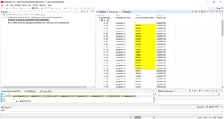
    I updated my Projekt according to your hints. Please find below the updated file with the main() function. Unfortunatly I still have problems with the execution time as you can see in the picture attached below. I recorded the cycle times to an array named cyclesTemp. As you can see the cycle times beginn with a higher cycle timen and go down to a smaler cycle times and then start again with a higher cycle time to go down again to a smaler cycle time. This behaviour seems to be cyclic. Is there any reason in the main() function for this behaviour? Also I found out, that with the actual configuration of the DMA control pakets the data in the RXDATA buffers do not match to the TXDATA buffers. The coded check in line 370 fails.

    Testting your CCS Project brings up, that it does not transfer the whole content of the TXDATA buffers with a length of 1024 words. Updating it to transmit the whole length of 1024 word leeds to the same problems described above. Could you please extend your project to transmitt the whole lengt of the TXDATA buffers and measure the cycle times?

    /* USER CODE BEGIN (0) */
    /* USER CODE END */
    
    /* Include Files */
    
    #include "HL_sys_common.h"
    
    /* USER CODE BEGIN (1) */
    #include "HL_mibspi.h"
    #include "HL_sys_dma.h"
    #include "HL_het.h"
    #include "HL_reg_het.h"
    #include "HL_sys_pmu.h"
    
    /* example data Pattern configuration */
    #define D_SIZE      128
    #define BUFFER_SIZE 1024
    
    void loadDataPattern(uint32 psize, uint16* pptr);
    void mibspiEnableInternalLoopback(mibspiBASE_t *mibspi);
    void dmaConfigCtrlPacket(uint32 sadd,uint32 dadd,uint32 dsize);
    void mibspiDmaConfig(mibspiBASE_t *mibspi,uint32 channel, uint32 txchannel, uint32 rxchannel);
    
    #pragma SET_DATA_SECTION(".sharedRAM")
    uint16 TXDATA[BUFFER_SIZE];         /* transmit buffer in sys ram */
    uint16 RXDATA[BUFFER_SIZE]= {0};    /* receive  buffer in sys ram */
    uint16 TXDATA2[BUFFER_SIZE];         /* transmit buffer in sys ram */
    uint16 RXDATA2[BUFFER_SIZE]= {0};    /* receive  buffer in sys ram */
    uint16 TXDATA3[BUFFER_SIZE];         /* transmit buffer in sys ram */
    uint16 RXDATA3[BUFFER_SIZE]= {0};    /* receive  buffer in sys ram */
    uint16 TXDATA4[BUFFER_SIZE];         /* transmit buffer in sys ram */
    uint16 RXDATA4[BUFFER_SIZE]= {0};    /* receive  buffer in sys ram */
    #pragma SET_DATA_SECTION()
    
    static g_dmaCTRL g_dmaCTRLPKT1, g_dmaCTRLPKT2;    /* dma control packet configuration stack */
    
    static uint32 cycles, cycles_cal;
    static uint32 cyclesTemp[1024];
    
    /* USER CODE END */
    
    /** @fn void main(void)
    *   @brief Application main function
    *   @note This function is empty by default.
    *
    *   This function is called after startup.
    *   The user can use this function to implement the application.
    */
    
    /* USER CODE BEGIN (2) */
    /* USER CODE END */
    
    void main(void)
    {
    /* USER CODE BEGIN (3) */
    
       uint32 i;
       uint32 j;
       uint32 m;
    
       _pmuInit_();
    
       /* - creating a data chunk in system ram to start with ... */
       loadDataPattern(BUFFER_SIZE,&TXDATA[0]);
       loadDataPattern(BUFFER_SIZE,&TXDATA2[0]);
       loadDataPattern(BUFFER_SIZE,&TXDATA3[0]);
       loadDataPattern(BUFFER_SIZE,&TXDATA4[0]);
    
       clearDataPattern(BUFFER_SIZE,&RXDATA[0]);
       clearDataPattern(BUFFER_SIZE,&RXDATA2[0]);
       clearDataPattern(BUFFER_SIZE,&RXDATA3[0]);
       clearDataPattern(BUFFER_SIZE,&RXDATA4[0]);
    
       //hetInit();
       //pwmSetDuty(hetRAM1, 0, 1);
    
       /* - initializing mibspi - enabling tg 0 , length 127 (halcogen file)*/
       mibspiInit();
    
       /* - enabling loopback ( this is to emulate data transfer without external wires */
       mibspiEnableInternalLoopback(mibspiREG1);
       mibspiEnableInternalLoopback(mibspiREG2);
       mibspiEnableInternalLoopback(mibspiREG3);
       mibspiEnableInternalLoopback(mibspiREG4);
    
       /* - configuring dma control packets   */
       g_dmaCTRLPKT1.SADD      = (uint32)TXDATA;    /* source address             */
       g_dmaCTRLPKT1.DADD      = (uint32)&(mibspiRAM1->tx[0].data);    /* destination  address       */
       g_dmaCTRLPKT1.CHCTRL    = 0;                 /* channel control            */
       g_dmaCTRLPKT1.FRCNT	   = 8;//1;                 /* frame count                */
       g_dmaCTRLPKT1.ELCNT     = D_SIZE;//32;//D_SIZE;            /* element count              */
       g_dmaCTRLPKT1.ELDOFFSET = 4;                 /* element destination offset */
       g_dmaCTRLPKT1.ELSOFFSET = 0;		            /* element destination offset */
       g_dmaCTRLPKT1.FRDOFFSET = 0;		            /* frame destination offset   */
       g_dmaCTRLPKT1.FRSOFFSET = 0;                 /* frame destination offset   */
       g_dmaCTRLPKT1.PORTASGN  = PORTA_READ_PORTB_WRITE;
       g_dmaCTRLPKT1.RDSIZE    = ACCESS_16_BIT;//ACCESS_64_BIT;	    /* read size                  */
       g_dmaCTRLPKT1.WRSIZE    = ACCESS_16_BIT; 	/* write size                 */
       g_dmaCTRLPKT1.TTYPE     = FRAME_TRANSFER ;   /* transfer type              */
       g_dmaCTRLPKT1.ADDMODERD = ADDR_INC1;         /* address mode read          */
       g_dmaCTRLPKT1.ADDMODEWR = ADDR_OFFSET;       /* address mode write         */
       g_dmaCTRLPKT1.AUTOINIT  = AUTOINIT_ON;       /* autoinit                   */
    
       g_dmaCTRLPKT2.SADD      = (uint32)&(mibspiRAM1->rx[0].data);    /* source address             */
       g_dmaCTRLPKT2.DADD      = (uint32)RXDATA;    /* destination  address       */
       g_dmaCTRLPKT2.CHCTRL    = 0;                 /* channel control            */
       g_dmaCTRLPKT2.FRCNT	   = 8;//1;                 /* frame count                */
       g_dmaCTRLPKT2.ELCNT     = D_SIZE;             /* element count              */
       g_dmaCTRLPKT2.ELDOFFSET = 0;                 /* element destination offset */
       g_dmaCTRLPKT2.ELSOFFSET = 4;		            /* element destination offset */
       g_dmaCTRLPKT2.FRDOFFSET = 0;		            /* frame destination offset   */
       g_dmaCTRLPKT2.FRSOFFSET = 0;                 /* frame destination offset   */
       g_dmaCTRLPKT2.PORTASGN  = PORTB_READ_PORTA_WRITE;
       g_dmaCTRLPKT2.RDSIZE    = ACCESS_16_BIT;	    /* read size                  */
       g_dmaCTRLPKT2.WRSIZE    = ACCESS_16_BIT;//ACCESS_64_BIT; 	/* write size                 */
       g_dmaCTRLPKT2.TTYPE     = FRAME_TRANSFER ;   /* transfer type              */
       g_dmaCTRLPKT2.ADDMODERD = ADDR_OFFSET;         /* address mode read          */
       g_dmaCTRLPKT2.ADDMODEWR = ADDR_INC1;       /* address mode write         */
       g_dmaCTRLPKT2.AUTOINIT  = AUTOINIT_ON;       /* autoinit                   */
    
       /* upto 32 control packets are supported. */
    
       /* - setting dma control packets */
       dmaSetCtrlPacket(DMA_CH0,g_dmaCTRLPKT2);
       dmaSetCtrlPacket(DMA_CH1,g_dmaCTRLPKT1);
    
       /* - setting the dma channel to trigger on h/w request */
       dmaSetChEnable(DMA_CH0, DMA_HW);
       dmaSetChEnable(DMA_CH1, DMA_HW);
    
       /* - configuring dma control packets   */
       g_dmaCTRLPKT1.SADD      = (uint32)TXDATA2;    /* source address             */
       g_dmaCTRLPKT1.DADD      = (uint32)&(mibspiRAM2->tx[0].data);    /* destination  address       */
       g_dmaCTRLPKT1.CHCTRL    = 0;                 /* channel control            */
       g_dmaCTRLPKT1.FRCNT     = 8;//1;                 /* frame count                */
       g_dmaCTRLPKT1.ELCNT     = D_SIZE;//32;//D_SIZE;            /* element count              */
       g_dmaCTRLPKT1.ELDOFFSET = 4;                 /* element destination offset */
       g_dmaCTRLPKT1.ELSOFFSET = 0;                 /* element destination offset */
       g_dmaCTRLPKT1.FRDOFFSET = 0;                 /* frame destination offset   */
       g_dmaCTRLPKT1.FRSOFFSET = 0;                 /* frame destination offset   */
       g_dmaCTRLPKT1.PORTASGN  = PORTA_READ_PORTB_WRITE;
       g_dmaCTRLPKT1.RDSIZE    = ACCESS_16_BIT;//ACCESS_64_BIT;     /* read size                  */
       g_dmaCTRLPKT1.WRSIZE    = ACCESS_16_BIT;     /* write size                 */
       g_dmaCTRLPKT1.TTYPE     = FRAME_TRANSFER ;   /* transfer type              */
       g_dmaCTRLPKT1.ADDMODERD = ADDR_INC1;         /* address mode read          */
       g_dmaCTRLPKT1.ADDMODEWR = ADDR_OFFSET;       /* address mode write         */
       g_dmaCTRLPKT1.AUTOINIT  = AUTOINIT_ON;       /* autoinit                   */
    
       g_dmaCTRLPKT2.SADD      = (uint32)&(mibspiRAM2->rx[0].data);    /* source address             */
       g_dmaCTRLPKT2.DADD      = (uint32)RXDATA2;    /* destination  address       */
       g_dmaCTRLPKT2.CHCTRL    = 0;                 /* channel control            */
       g_dmaCTRLPKT2.FRCNT     = 8;//1;                 /* frame count                */
       g_dmaCTRLPKT2.ELCNT     = D_SIZE;             /* element count              */
       g_dmaCTRLPKT2.ELDOFFSET = 0;                 /* element destination offset */
       g_dmaCTRLPKT2.ELSOFFSET = 4;                 /* element destination offset */
       g_dmaCTRLPKT2.FRDOFFSET = 0;                 /* frame destination offset   */
       g_dmaCTRLPKT2.FRSOFFSET = 0;                 /* frame destination offset   */
       g_dmaCTRLPKT2.PORTASGN  = PORTB_READ_PORTA_WRITE;
       g_dmaCTRLPKT2.RDSIZE    = ACCESS_16_BIT;     /* read size                  */
       g_dmaCTRLPKT2.WRSIZE    = ACCESS_16_BIT;//ACCESS_64_BIT;     /* write size                 */
       g_dmaCTRLPKT2.TTYPE     = FRAME_TRANSFER ;   /* transfer type              */
       g_dmaCTRLPKT2.ADDMODERD = ADDR_OFFSET;         /* address mode read          */
       g_dmaCTRLPKT2.ADDMODEWR = ADDR_INC1;       /* address mode write         */
       g_dmaCTRLPKT2.AUTOINIT  = AUTOINIT_ON;       /* autoinit                   */
    
       /* upto 32 control packets are supported. */
    
       /* - setting dma control packets */
       dmaSetCtrlPacket(DMA_CH2,g_dmaCTRLPKT2);
       dmaSetCtrlPacket(DMA_CH3,g_dmaCTRLPKT1);
    
       /* - setting the dma channel to trigger on h/w request */
       dmaSetChEnable(DMA_CH2, DMA_HW);
       dmaSetChEnable(DMA_CH3, DMA_HW);
    
       /* - configuring dma control packets   */
       g_dmaCTRLPKT1.SADD      = (uint32)TXDATA3;    /* source address             */
       g_dmaCTRLPKT1.DADD      = (uint32)&(mibspiRAM3->tx[0].data);    /* destination  address       */
       g_dmaCTRLPKT1.CHCTRL    = 0;                 /* channel control            */
       g_dmaCTRLPKT1.FRCNT     = 8;//1;                 /* frame count                */
       g_dmaCTRLPKT1.ELCNT     = D_SIZE;//32;//D_SIZE;            /* element count              */
       g_dmaCTRLPKT1.ELDOFFSET = 4;                 /* element destination offset */
       g_dmaCTRLPKT1.ELSOFFSET = 0;                 /* element destination offset */
       g_dmaCTRLPKT1.FRDOFFSET = 0;                 /* frame destination offset   */
       g_dmaCTRLPKT1.FRSOFFSET = 0;                 /* frame destination offset   */
       g_dmaCTRLPKT1.PORTASGN  = PORTA_READ_PORTB_WRITE;
       g_dmaCTRLPKT1.RDSIZE    = ACCESS_16_BIT;//ACCESS_64_BIT;     /* read size                  */
       g_dmaCTRLPKT1.WRSIZE    = ACCESS_16_BIT;     /* write size                 */
       g_dmaCTRLPKT1.TTYPE     = FRAME_TRANSFER ;   /* transfer type              */
       g_dmaCTRLPKT1.ADDMODERD = ADDR_INC1;         /* address mode read          */
       g_dmaCTRLPKT1.ADDMODEWR = ADDR_OFFSET;       /* address mode write         */
       g_dmaCTRLPKT1.AUTOINIT  = AUTOINIT_ON;       /* autoinit                   */
    
       g_dmaCTRLPKT2.SADD      = (uint32)&(mibspiRAM3->rx[0].data);    /* source address             */
       g_dmaCTRLPKT2.DADD      = (uint32)RXDATA3;    /* destination  address       */
       g_dmaCTRLPKT2.CHCTRL    = 0;                 /* channel control            */
       g_dmaCTRLPKT2.FRCNT     = 8;//1;                 /* frame count                */
       g_dmaCTRLPKT2.ELCNT     = D_SIZE;             /* element count              */
       g_dmaCTRLPKT2.ELDOFFSET = 0;                 /* element destination offset */
       g_dmaCTRLPKT2.ELSOFFSET = 4;                 /* element destination offset */
       g_dmaCTRLPKT2.FRDOFFSET = 0;                 /* frame destination offset   */
       g_dmaCTRLPKT2.FRSOFFSET = 0;                 /* frame destination offset   */
       g_dmaCTRLPKT2.PORTASGN  = PORTB_READ_PORTA_WRITE;
       g_dmaCTRLPKT2.RDSIZE    = ACCESS_16_BIT;     /* read size                  */
       g_dmaCTRLPKT2.WRSIZE    = ACCESS_16_BIT;//ACCESS_64_BIT;     /* write size                 */
       g_dmaCTRLPKT2.TTYPE     = FRAME_TRANSFER ;   /* transfer type              */
       g_dmaCTRLPKT2.ADDMODERD = ADDR_OFFSET;         /* address mode read          */
       g_dmaCTRLPKT2.ADDMODEWR = ADDR_INC1;       /* address mode write         */
       g_dmaCTRLPKT2.AUTOINIT  = AUTOINIT_ON;       /* autoinit                   */
    
       /* upto 32 control packets are supported. */
    
       /* - setting dma control packets */
       dmaSetCtrlPacket(DMA_CH4,g_dmaCTRLPKT2);
       dmaSetCtrlPacket(DMA_CH5,g_dmaCTRLPKT1);
    
       dmaReqAssign(DMA_CH4, DMA_REQ14);
       dmaReqAssign(DMA_CH5, DMA_REQ15);
    
       /* - setting the dma channel to trigger on h/w request */
       dmaSetChEnable(DMA_CH4, DMA_HW);
       dmaSetChEnable(DMA_CH5, DMA_HW);
    
       /* - configuring dma control packets   */
       g_dmaCTRLPKT1.SADD      = (uint32)TXDATA4;    /* source address             */
       g_dmaCTRLPKT1.DADD      = (uint32)&(mibspiRAM4->tx[0].data);    /* destination  address       */
       g_dmaCTRLPKT1.CHCTRL    = 0;                 /* channel control            */
       g_dmaCTRLPKT1.FRCNT     = 8;//1;                 /* frame count                */
       g_dmaCTRLPKT1.ELCNT     = D_SIZE;//32;//D_SIZE;            /* element count              */
       g_dmaCTRLPKT1.ELDOFFSET = 4;                 /* element destination offset */
       g_dmaCTRLPKT1.ELSOFFSET = 0;                 /* element destination offset */
       g_dmaCTRLPKT1.FRDOFFSET = 0;                 /* frame destination offset   */
       g_dmaCTRLPKT1.FRSOFFSET = 0;                 /* frame destination offset   */
       g_dmaCTRLPKT1.PORTASGN  = PORTA_READ_PORTB_WRITE;
       g_dmaCTRLPKT1.RDSIZE    = ACCESS_16_BIT;//ACCESS_64_BIT;     /* read size                  */
       g_dmaCTRLPKT1.WRSIZE    = ACCESS_16_BIT;     /* write size                 */
       g_dmaCTRLPKT1.TTYPE     = FRAME_TRANSFER ;   /* transfer type              */
       g_dmaCTRLPKT1.ADDMODERD = ADDR_INC1;         /* address mode read          */
       g_dmaCTRLPKT1.ADDMODEWR = ADDR_OFFSET;       /* address mode write         */
       g_dmaCTRLPKT1.AUTOINIT  = AUTOINIT_ON;       /* autoinit                   */
    
       g_dmaCTRLPKT2.SADD      = (uint32)&(mibspiRAM4->rx[0].data);    /* source address             */
       g_dmaCTRLPKT2.DADD      = (uint32)RXDATA4;    /* destination  address       */
       g_dmaCTRLPKT2.CHCTRL    = 0;                 /* channel control            */
       g_dmaCTRLPKT2.FRCNT     = 8;//1;                 /* frame count                */
       g_dmaCTRLPKT2.ELCNT     = D_SIZE;             /* element count              */
       g_dmaCTRLPKT2.ELDOFFSET = 0;                 /* element destination offset */
       g_dmaCTRLPKT2.ELSOFFSET = 4;                 /* element destination offset */
       g_dmaCTRLPKT2.FRDOFFSET = 0;                 /* frame destination offset   */
       g_dmaCTRLPKT2.FRSOFFSET = 0;                 /* frame destination offset   */
       g_dmaCTRLPKT2.PORTASGN  = PORTB_READ_PORTA_WRITE;
       g_dmaCTRLPKT2.RDSIZE    = ACCESS_16_BIT;     /* read size                  */
       g_dmaCTRLPKT2.WRSIZE    = ACCESS_16_BIT;//ACCESS_64_BIT;     /* write size                 */
       g_dmaCTRLPKT2.TTYPE     = FRAME_TRANSFER ;   /* transfer type              */
       g_dmaCTRLPKT2.ADDMODERD = ADDR_OFFSET;         /* address mode read          */
       g_dmaCTRLPKT2.ADDMODEWR = ADDR_INC1;       /* address mode write         */
       g_dmaCTRLPKT2.AUTOINIT  = AUTOINIT_ON;       /* autoinit                   */
    
       /* upto 32 control packets are supported. */
    
       /* - setting dma control packets */
       dmaSetCtrlPacket(DMA_CH6,g_dmaCTRLPKT2);
       dmaSetCtrlPacket(DMA_CH7,g_dmaCTRLPKT1);
    
       dmaReqAssign(DMA_CH6, DMA_REQ24);
       dmaReqAssign(DMA_CH7, DMA_REQ25);
    
       /* - setting the dma channel to trigger on h/w request */
       dmaSetChEnable(DMA_CH6, DMA_HW);
       dmaSetChEnable(DMA_CH7, DMA_HW);
    
       //dmaReqAssign(DMA_CH0, DMA_REQ0);
       //dmaReqAssign(DMA_CH1, DMA_REQ1);
    
       /* - configuring the mibspi dma , channel 0 , tx line -0 , rxline -1     */
       /* - refer to the device data sheet dma request source for mibspi tx/rx  */
       mibspiDmaConfig(mibspiREG1,0,0,1);
       mibspiDmaConfig(mibspiREG2,0,0,1);
       mibspiDmaConfig(mibspiREG3,0,0,1);
       mibspiDmaConfig(mibspiREG4,0,0,1);
    
    //   dmaSetPriority(DMA_CH4, HIGHPRIORITY);
    //   dmaSetPriority(DMA_CH5, HIGHPRIORITY);
    //   dmaSetPriority(DMA_CH6, HIGHPRIORITY);
    //   dmaSetPriority(DMA_CH7, HIGHPRIORITY);
    //   dmaSetPriority(DMA_CH0, LOWPRIORITY);
    //   dmaSetPriority(DMA_CH1, LOWPRIORITY);
    //   dmaSetPriority(DMA_CH2, LOWPRIORITY);
    //   dmaSetPriority(DMA_CH3, LOWPRIORITY);
    
       dmaEnable();
       hetInit();
       pwmSetDuty(hetRAM1, 0, 1);
    
       i = 0;
    
    while(1)
    {
       i++;
    
       /*Reset Cycle Counter */
       _pmuResetCounters_();
       /*Start Cycle Counter */
       _pmuStartCounters_(pmuCYCLE_COUNTER);
       /*Stop Cycle Counter */
       _pmuStopCounters_(pmuCYCLE_COUNTER);
       /* read the CNNT cycle for calibration */
       cycles_cal = _pmuGetCycleCount_();
    
       _pmuResetCounters_();
    
       /*Start Cycle Counter */
       _pmuStartCounters_(pmuCYCLE_COUNTER);
    
       pwmSetDuty(hetRAM1, 0, 100);
    
       /* - start the mibspi transfer tg 0 */
       mibspiTransfer(mibspiREG1,0 );
    
       while(dmaGetInterruptStatus(DMA_CH0, HBC) == FALSE);
    
       mibspiTransfer(mibspiREG2,0 );
    
       while(dmaGetInterruptStatus(DMA_CH2, HBC) == FALSE);
    
       mibspiTransfer(mibspiREG3,0 );
    
       while(dmaGetInterruptStatus(DMA_CH4, HBC) == FALSE);
    
       mibspiTransfer(mibspiREG4,0 );
    
       while(dmaGetInterruptStatus(DMA_CH6, BTC) == FALSE);
    
       //while(dmaGetInterruptStatus(DMA_CH6, BTC) == FALSE);
       //while(dmaGetInterruptStatus(DMA_CH0, BTC) == FALSE);
       //while(dmaGetInterruptStatus(DMA_CH2, BTC) == FALSE);
       //while(dmaGetInterruptStatus(DMA_CH4, BTC) == FALSE);
    
       /*Stop Cycle Counter */
       _pmuStopCounters_(pmuCYCLE_COUNTER);
       /* read the CNNT cycle */
       cycles = _pmuGetCycleCount_();
       /*corrected cyles */
       cycles = cycles - cycles_cal;
    
       if(i < 1024)
       {
          cyclesTemp[i] = cycles;
       }
    
       pwmSetDuty(hetRAM1, 0, 1);
    
       mibspiDisableTransfer(mibspiREG1,0);
       mibspiDisableTransfer(mibspiREG2,0);
       mibspiDisableTransfer(mibspiREG3,0);
       mibspiDisableTransfer(mibspiREG4,0);
    
       dmaREG->BTCFLAG = 0xFFFFFFFF;
       dmaREG->HBCFLAG = 0xFFFFFFFF;
     
       dmaDisable();
    
       mibspiDmaConfig(mibspiREG1,0,0,1);
       mibspiDmaConfig(mibspiREG2,0,0,1);
       mibspiDmaConfig(mibspiREG3,0,0,1);
       mibspiDmaConfig(mibspiREG4,0,0,1);
    
       m = 0x00000000;
    
       for(j = 0; j < BUFFER_SIZE; j++)
       {
           if((TXDATA[j] != RXDATA[j]) || (TXDATA2[j] != RXDATA2[j]) || (TXDATA3[j] != RXDATA3[j]) || (TXDATA4[j] != RXDATA4[j]))
           {
              m = 0xFFFFFFFF;
           }
       }
    
       clearDataPattern(BUFFER_SIZE,&RXDATA[0]);
       clearDataPattern(BUFFER_SIZE,&RXDATA2[0]);
       clearDataPattern(BUFFER_SIZE,&RXDATA3[0]);
       clearDataPattern(BUFFER_SIZE,&RXDATA4[0]);
    
       dmaEnable();
    }
       pwmStop(hetRAM1, 0);
    
       while(1); /* loop forever */
    
    /* USER CODE END */
    }
    
    /* USER CODE BEGIN (4) */
    /** void mibspiEnableLoopback(mibspiBASE_t *mibspi )
    *
    *   enabling internal loopback on mibspix
    */
    void mibspiEnableInternalLoopback(mibspiBASE_t *mibspi )
    {
    	/* enabling internal loopback */
        mibspi->GCR1 |= 1U << 16U;
    }
    
    void mibspiDisableTransfer(mibspiBASE_t * mibspi, uint32_t group)
    {
       mibspi->TGCTRL[group] = (mibspi->TGCTRL[group] & 0x7FFFFFFFU);
    }
    
    /** void mibspiDmaConfig(mibspiBASE_t *mibspi,uint32 channel, uint32 txchannel, uint32 rxchannel)
    *
    *   configuring mibspi dma with
    *
    *       channel   > mibspi dma channel number
    *       txchannel > transmit channel dedicated for mibspi
    *       rxchannel > receive  channel dedicated for mibspi
    */
    void mibspiDmaConfig(mibspiBASE_t *mibspi,uint32 channel, uint32 txchannel, uint32 rxchannel)
    {
    	uint32 bufid  = D_SIZE - 1;
    	uint32 icount = 0;
    
        /* setting large count */
        mibspi->DMACNTLEN = 0x00000001;
    
        /*  setting initial count of DMA transfers */
        mibspi->DMACOUNT[channel] = 8 << 16; //BUFFER_SIZE << 16;
    
    	/* setting transmit and receive channels */
    	mibspi->DMACTRL[channel] |= (((rxchannel<<4)|txchannel) << 16);
    
    	/* enabling transmit and receive dma */
    	mibspi->DMACTRL[channel] |=  0x8000C000;
    
    	/* setting Initial Count of DMA transfers and the buffer utilized for DMA transfer */
    	mibspi->DMACTRL[channel] |=  (icount << 8) |(bufid<<24);
    
    }
    
    
    /** void loadDataPattern(uint32 psize, uint16* pptr)
    *
    *   loading a randam data chunk into system ram
    *
    *     pptr  > sys ram address
    *     psize > chunkl size
    *
    */
    void loadDataPattern(uint32 psize, uint16* pptr)
    {
    	unsigned int i;
    
    	for(i= 0; i < psize; i++)
    	{
    	    *pptr = i;
    	    pptr++;
    	}
     }
    
    void clearDataPattern(uint32 psize, uint16* pptr)
    {
        unsigned int i;
    
        for(i= 0; i < psize; i++)
        {
            *pptr = 0;
            pptr++;
        }
    }
    /* USER CODE END */
    

  • Also I found out, that with the actual configuration of the DMA control pakets the data in the RXDATA buffers do not match to the TXDATA buffers.

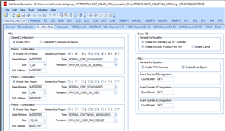
    Is the Cortex-R5 cache enabled in your HALCoGen project?

    In the TMS570LC4357_MibSPI_DMA_Execution_Time\TMS570LC4357_MibSPI1&3_DMA.hcg example project from  the Cache is disabled:

    Having the cache enabled and the SHAREDRAM memory region marked as cacheable in the MPU could have the following effects:

    a. Reading back the RXDATA buffers not matching the TXDATA buffers. Reading the TRM I not yet sure if the DMA supports hardware cache coherency.

    b. Cycle times varying.

  • Hi Raheem,,

    I changed the frame count (F_COUNT) to 8 for transferring a block of data with 1024 half-words, and I noticed the difference of the execution time. 

    If the F_COUNT =1, the time for transferring blocks block 1, block2, ... block 10) is same.

    If the F_COUNT =4, the transfer time decreases from block #1 to block #4. The transfer time of block#5 gets back to as long as the block #1

    If the F_COUNT =8, the transfer time decreases from block #1 to block #8. The transfer time of block#9 gets back to as long as the block #1

    I am not sure what causes this behavior, and I will do more research and test later.

  • Hi QJ,

    thanks for your answer. That is exactly what I am observing as well. I'm curious to see what you find out. I disabled the cache with the fact, that the cycle times still vary.

    Thank you very much for your help.