This thread has been locked.

If you have a related question, please click the "Ask a related question" button in the top right corner. The newly created question will be automatically linked to this question.

TM4C123GH6PGE: The SSI/SPI has CLK and IO output waveform issues during operation

Part Number: TM4C123GH6PGE

Hi team,

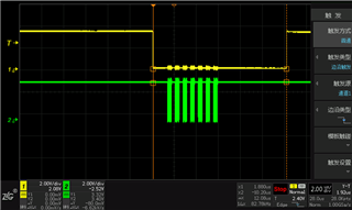
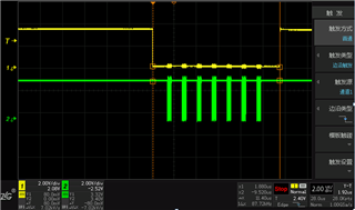
Using this M4 for SPI use, using oscilloscope for frequency and TX measurement, it is found that the waveform cannot be "square wave".

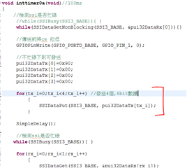
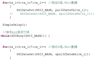
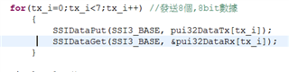
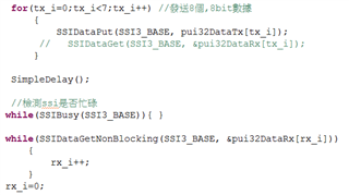
Causes the data resolution to be abnormal and the configuration is as follows:

Frequency: 80Mhz SPI: 20Mhz

The waveform is the same on the board made by customer as the TivaTm TM4C123G development board test (no load measurement on the circuit SPI pin).

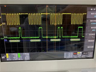
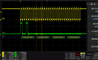
The waveform data is basically matched to the program transmit and the frequency measurement is 20Mhz. Only the frequency cannot be square. As this 20Mhz is decreasing, the waveform will gradually become square

So the customer would like to know is there a maximum output frequency for this IC? ? Or does it need to work with an external circuit? 

Could you help check this case? Thanks.

Best Regards,

Cherry

  • Hi Cherry,

      The maximum SPI clock is spec'ed for 25Mhz. Therefore, 20Mhz should be fine. The waveform looks ok to me. Please make sure both the master and slave are configured for exactly the same SPICLK phase and polarity. This should give slave half cycle of setup time to sample the data. 

      The default drive strength chosen for SSI pins is 2mA. See below.  I think higher drive strength will help. You might need to modify for higher drive strength like 4mA to see if it it helps. You will need to manually configure the port instead of using the TivaWare library. 

    //*****************************************************************************
    //
    //! Configures pin(s) for use by the SSI peripheral.
    //!
    //! \param ui32Port is the base address of the GPIO port.
    //! \param ui8Pins is the bit-packed representation of the pin(s).
    //!
    //! The SSI pins must be properly configured for the SSI peripheral to function
    //! correctly. This function provides a typical configuration for those
    //! pin(s); other configurations may work as well depending upon the board
    //! setup (for example, using the on-chip pull-ups).
    //!
    //! The pin(s) are specified using a bit-packed byte, where each bit that is
    //! set identifies the pin to be accessed, and where bit 0 of the byte
    //! represents GPIO port pin 0, bit 1 represents GPIO port pin 1, and so on.
    //!
    //! \note This function cannot be used to turn any pin into a SSI pin; it only
    //! configures a SSI pin for proper operation. Note that a GPIOPinConfigure()
    //! function call is also required to properly configure a pin for the SSI
    //! function.
    //!
    //! \note A subset of GPIO pins on Tiva devices, notably those used by the
    //! JTAG/SWD interface and any pin capable of acting as an NMI input, are
    //! locked against inadvertent reconfiguration. These pins must be unlocked
    //! using direct register writes to the relevant GPIO_O_LOCK and GPIO_O_CR
    //! registers before this function can be called. Please see the ``gpio_jtag''
    //! example application for the mechanism required and consult your part
    //! datasheet for information on affected pins.
    //!
    //! \return None.
    //
    //*****************************************************************************
    void
    GPIOPinTypeSSI(uint32_t ui32Port, uint8_t ui8Pins)
    {
    //
    // Check the arguments.
    //
    ASSERT(_GPIOBaseValid(ui32Port));

    //
    // Make the pin(s) be peripheral controlled.
    //
    GPIODirModeSet(ui32Port, ui8Pins, GPIO_DIR_MODE_HW);

    //
    // Set the pad(s) for standard push-pull operation.
    //
    GPIOPadConfigSet(ui32Port, ui8Pins, GPIO_STRENGTH_2MA, GPIO_PIN_TYPE_STD);

  • Hi Charles,

    Thanks for your support!

    And here's an additional question:

    The customer does 4 8bit loop sending in the program and finds that at 20Mhz the waveform will be disconnected in the middle. However, by lowering the frequency, such as10Mhz, under the same program, the 4 8bit waveforms are continuous. So is there a way to improve continuity at 20Mhz?

    The program is as follows, in a 100ms timer, 4 8bit data send for SPI-> -delay half cycle > detect if busy-> do a data acquisition, and so on, loop:

    (The 5 lines of Chinese separately means:

    Line 1: Detects if the SSI is busy

    Line 2: Pull CE low before sending

    Line 3: Can be sent when not busy

    Line 4: Send 4 8bit data

    Line 5: Detects if the SSI is busy)

    The figure above is continuous waveform at 10Mhz, and it's clear there is no interrupt between each byte.

    Thanks and Best Regards,

    Cherry

  • Hi Cherry,

      Please refer to the datasheet for details. As you can see for continuous transfers there will be some idle time between two transfers. See below diagram from datasheet.

     Also see below description. 

    In the case of a single word transmission, after all bits of the data word have been transferred, the
    SSInFss line is returned to its idle High state one SSInClk period after the last bit has been
    captured.
    However, in the case of continuous back-to-back transmissions, the SSInFss signal must be pulsed
    High between each data word transfer because the slave select pin freezes the data in its serial
    peripheral register and does not allow it to be altered if the SPH bit is clear. Therefore, the master
    device must raise the SSInFss pin of the slave device between each data transfer to enable the
    serial peripheral data write. On completion of the continuous transfer, the SSInFss pin is returned
    to its idle state one SSInClk period after the last bit has been captured.

  • Hi Charles,

    Since SSIDataGet does not generate CLK when it is used, so would you like to recommend when to use it?

    There are several ways to send and read:

    1. Send at once, read at once: (the figure left is FSS, and the right is LCK)

    2. transmitting when receiving:(the figure left is FSS, and the right is LCK)

    3. Instead of SSIDataGet, use SSIDataGetNonblocking to receive FIFO:(the figure left is FSS, and the right is LCK)

    All 3 can work correctly, the difference is that the order is different. So it also causes different waveforms, after calculating,it's just the difference in the point at which the SSIDataGet executes.

    So which one would you recommend to use?

    Thanks and Best Regards,

    Cherry

  • Hi Cherry,

      At three should work. The SPI has an FIFO. If you use method 1, you can store multiple data to transmit at once. I think it is more efficient.