This thread has been locked.

If you have a related question, please click the "Ask a related question" button in the top right corner. The newly created question will be automatically linked to this question.

TM4C1294NCPDT: The controller has detected a cable break far-from itself.

Part Number: TM4C1294NCPDT
Other Parts Discussed in Thread: EK-TM4C1294XL

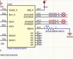
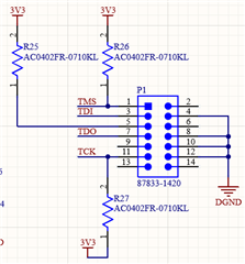
I am using a XDS-100 V2 to connect to a TM4C1294NCPDT microcontroller through JTAG.

I am getting the following error message,

[Start]

Execute the command:

%ccs_base%/common/uscif/dbgjtag -f %boarddatafile% -rv -o -F inform,logfile=yes -S pathlength -S integrity

[Result]


-----[Print the board config pathname(s)]------------------------------------

C:\Users\gaaoce1\AppData\Local\TEXASI~1\
CCS\ccs1011\0\0\BrdDat\testBoard.dat

-----[Print the reset-command software log-file]-----------------------------

This utility has selected a 100- or 510-class product.
This utility will load the adapter 'jioserdesusb.dll'.
The library build date was 'May 7 2020'.
The library build time was '21:10:18'.
The library package version is '9.2.0.00002'.
The library component version is '35.35.0.0'.
The controller does not use a programmable FPGA.

An error occurred while hard opening the controller.

-----[An error has occurred and this utility has aborted]--------------------

This error is generated by TI's USCIF driver or utilities.

The value is '-183' (0xffffff49).
The title is 'SC_ERR_CTL_CBL_BREAK_FAR'.

The explanation is:
The controller has detected a cable break far-from itself.
The user must connect the cable/pod to the target.

[End]

I am only getting a small blip on TMS, TCK, and TDO when clicking the Verify "Connection". TMS (Blue), TCK (Yellow), TDI (Red), and TDO (Green). 

VTRef is a 3.2V,


VDDC is at 1.2V,

Does anyone have a suggestion as to why I am getting this error?

  • Hello JAOverstreet,

    TDO should have a 10kOhm pulldown on it. Pin 5 resistance is recommended to be 100 ohms and other pullups are recommended to be 10k ohms. I am not certain what value of resistor is used, but I do see there is no difference between the three resistors so I assume Pin 5 has 10k as well.

    One more thing to look at is since you have a TM4C1294NCPDT, you need the 4.7kOhm resistor for RBIAS installed per Errata item ETH#03: https://www.ti.com/lit/pdf/spmz850

    Please resolve these identified / potential hardware issues and see if the connection can be established.

    Best Regards,

    Ralph Jacobi

  • Ralph,

    I have modified the board per your schematic, but am still getting the same error message. You are correct resistors R25, R26,R27 were all 10k. I reduced R25 to a 100 ohm and added a 10k pull down resistor to TDO. RBIAS has been populated on the PCB and is 4.87k.

    I am getting the same results on the scope,

    Blue (TMS), Red (TDI), Green (TDO), Yellow (TCK)

  • Hi JAOverstreet,

    Oddly TDI was past depicted as pin 8 on EVM schematic, not pin 3 as shown above and pins 3,5,9 ground. TMS/SWDIO pin 2 with 10k pullup, TCK/SWCLK pin 4 with 10k pullup. It works great with 1294 EVM port U6 configured external JTAG, remove R40 and R6-R16 0R. I cut trace near U6 pin 1 since target JTAG supplies 3v3 too.

  • The problem turned out to be a wiring issue between the JTAG connector on the XDS100 and the custom board.

  • Hello JAOverstreet,

    I was in the process of reviewing past instances of that SC_ERR_CTL_CBL_BREAK_FAR issue and that was the recurring theme. Glad you were able to discover that because I was just about to reply with guidance to verify the wiring/header pinouts.

    Best Regards,

    Ralph Jacobi

  • The problem turned out to be a wiring issue between the JTAG connector on the XDS100 and the custom board.

    What pin did you find in error?

    You might discover the XDS100 does not work so well to debug TM4C1294 as does XDS110 built on the TI launch pad (EVM). Perhaps Ralph can confirm why TDI is shown to be on a different pin in TM4C1294 EVM schematic.

  • Hello Gl,

    Perhaps Ralph can confirm why TDI is shown to be on a different pin in TM4C1294 EVM schematic.

    The pinout in question for this post is the 14-pin TI connector which I posted the proper schematic of above.

    The EK-TM4C1294XL JTAG connector is a 10-pin Arm connector which has a different pinout:

    All of these pinouts are documented in our JTAG User's Guide: https://www.ti.com/lit/pdf/spma075

    Best Regards,

    Ralph Jacobi

  • Hi Ralph,

    Yet my XDS100v1 has 10 pin ribbon cable female plug, was changed to 14 pin XDS100v2?  The XDS100v1 could not unlock the TM4C1294 as I recall using launch pad JTAG XDS110 for that reason. Nice PDF to have thanks that too.

    Happy holidays keep well protected Mask