This thread has been locked.

If you have a related question, please click the "Ask a related question" button in the top right corner. The newly created question will be automatically linked to this question.

TMS570LS1114: Clock does not get locked

Part Number: TMS570LS1114
Other Parts Discussed in Thread: HALCOGEN

Hey,

We are starting to use TMS570LS1114ZWT, in the past we worked with TMS570LS0914PGE.

Our Oscillator has 12MHz. We verified that with an oscilloscope.

With Halcogen we generated a initial Project. We tried to set the core Frequency to 120Mhz(and also 160MHz and 180MHz). However, we are using this 120MHz in our old project. Our configurations are below.

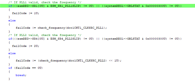
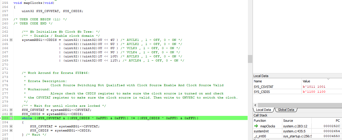
When we run our genereated code. It stack at the point when the programm waits until the clocks are locked.

Do you have an idea how we can check that the hardware is designed correctly? are there some points which should be measured?

Or how can we verify that there are no missing configuration settings in halcogen?


Here are my configurations:

Best regards,

Thorben

  • Hi Thorben,

    The workaround for SSWF021#45 addresses the issue where the PLL on some parts fails to start. The PLL can lose lock if an oscillator fault is detected, or if the PLL configuration is changed significantly versus the one that is being used for operation (NR, NF or ODPLL settings).

    Some suggestions for further debug:

    1. You can configure the debugger to halt upon a write to the PLL control register 1. This will help you identify all the places in software where the PLLCTL1 register is being written. Then you can compare the values being written to make sure that these are as expected.
    2. You can use the "Clock Test Mode" to output different clock sources and domains on to the ECLK pin. Please output the HF LPO to make sure that it is around 9.6MHz (typically).
    3. Enable response to an oscillator fault detected. e.g. reset on oscillator fault. Then monitor the nRST pin to see if it is asserted signaling an oscillator fault.
  • Hey QJ Wang,
    1) PLLCTL1 is set like the configuration.
    We operate with the solution of the workaround for SSWF021#45 of Halcogen(04.07.01).
    By default both PLLs will be checked, Is this recommended?
    We propably dont need both PLLs.
    In _errata_SSWF021_45_both_plls both PLLs fail:
    The values of the register are:
    esmReg->SR1[0]  = 0x400,
    esmReg->SR4[0]  = 0x0; and 
    systemREG->GBLSTAT = 0x300
    2) ClockTest (if PLLs are not checked):
    when we use ECLK as test signal: We have seen HF LPO was 10Mhz and LF LPO was 80kHz. And the Oszilator was 12MHz. This match with the configuration in Halcogen.
    However, we can not see a signal on ECLK if we use PLL1 as output. Probability because the bit for PLL1 in the register CVSTAT was 0.
    After trying to run PLL1 correctly, we tried to run the workaround after PLL has been setup..- Unfortunately, we have the same Issue here:
    Is there a more effective way to reset the device?
    3) Has not been tested, jet.
    Best Regards,
    Thorben

    --Edit:
    to 2) "However, we can not see a signal on ECLK if we use PLL1 as output. Probability because the bit for PLL1 in the register CVSTAT was 0."
    PLL was not enabled at the time of the test
  • Hi QJ,

    Good Day. I would like to follow up about the customer's query. Thank you very much.

    Best Regards,

    Ray Vincent

  • additional Information:
    i run the software on Hercules TMS570LS12x LaunchPad. In this case i do not have this clock issue.

    Edit:

    We have checked the hardware. VCCPLL is not connected to Vcore.

    Can we use the PLL without VCCPLL ?

    probably this is the reason that the clocks cant get locked. We will try it, and let you know, if this helps.

  • Hi QJ,

    Good Day. I would like to follow up again about the customer's query. Thank you very much.

    Best Regards,

    Ray Vincent

  • Hi Thorben,

    The VCCPLL must be provided. It is dedicated core supply for PLLs (PLL1 and PLL2).

  • Thank you for your help.