Other Parts Discussed in Thread: HALCOGEN
continuing the previously posted question:
TMS570LC4357: SPI CS issue when configured as SPI Functional
Hi Wang,
In our application for the TMS570LC4357 processor, we are interfacing the Serial Flash "S25FL256S" via SPI3 with the baud rate of 5MHz. In our system the clock configuration(in MHz) are : OSC = 20, PLL1 = 180, GCLK = 180, HCLK = 90 and VCLK1 = 90. The SPI is used in 4-Pin Mode i.e. SPI3CLK, SPI3SIMO, SPI3MISO & SPI3CS_0, and the SPI3 Pin configuration registers i.e. (PC0-PC8) are used only for configuring these 4 pins accordingly. Here, SPI3 is in Master Mode and the CSHOLD bit kept true.
When we are trying the communicate with the external serial flash, by configuring the SPI3CS_0 as functional and keeping the CSNR value as 0xFE, at the 5MHz rate we are not receiving the proper data configured, and every time it is getting read as 0xFF. We tried reducing the baud rate even we tried by configuring the different CSNR values such as 1,0xFF and 0xFD but still not able to establish the proper communication.
However, when we tried by configuring the SPI3CS_0 as GIO and then manually asserting/deasserting the chip selects before reading/writing the data (keeping the same configuration as mentioned in 1st paragraph), in that case, we are properly able to establish the communication with that external chip.
Thus, request you to help me in understanding, where exactly could it be going wrong whenever we are using the ChipSelect as SPI functional and how can I establish the communication using just the SPI as functional not as a GIO.
Regards,
Shivam
I'm encountering the same issue on my end. I've used halcogen to generate HL_spi.c and NOT HL_mibspi.c. I current have an external spi-based DAC connect on spi1. The I'm using CS[2] to communicate with the DAC. I'm able to manually manipulate the CS[2] gpio and successfully communicate, but it does not work when the CS is in functional mode.
I have C2TDELAY and T2CDELAY configured for 255 (I've tried various other values to include 3, 10, 50, 100 etc.), WDEL=1. I've tried CSNR =0 as well as CSNR = 0x3b (CS[2] only see table 28-25)
My clock after scaling is 1Mhz. Again things work in manual mode, just not functional. I did some probing of the CS line and it looks to toggle, but I'm reading back erroneous values.
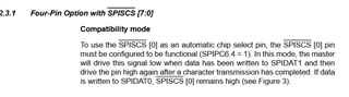
Is toggling of CS[2] in COMPATIBILITY MODE a valid operation? This document has me questioning the functionality:
(See 2.3.1)