Part Number: TMS570LS1224
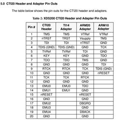
How to map my JTAG signals on the board ( EMU0, EMU1 , RTCK , TCK ,TD I,TDO ,TMS) to the XDS200 DEBUG PROBE with CTI 20 Pin connector?
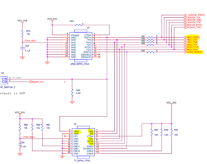
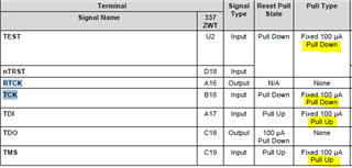
what are the pull up and pull down resistors required on the signals?
what are the essential signals for proper working and how to also map the additional signals from my design (like JTAGsel, NTRST, RTCK)?
I am using TMS5701224CPGEQQ1 and XDS200 Debug probe . I will be mapping to CTI-20 PIn on XDS200 debug probe.