This thread has been locked.

If you have a related question, please click the "Ask a related question" button in the top right corner. The newly created question will be automatically linked to this question.

TM4C129ENCPDT: ICDI interface damaging TM4C processor

Part Number: TM4C129ENCPDT
Other Parts Discussed in Thread: EK-TM4C1294XL, LMFLASHPROGRAMMER, TM4C1294NCPDT

I am having problems with the ICDI JTAG interface damaging both the ICDI programmer and my TM4C129ENCPDT processor.

I am debugging updating a bootloader in my own CODE at Flash address 0.

After I program the through a serial port and then update the flash, the next connect with ICDI fails.

I have now had two of the ICDI boards fail and two of the TM4C129ENCPDT processors fail.

As the only connection between these is the ICDI JTAG interface, I can only conclude that the JTAG pins on the processor and the output pins on the ICDI board are somehow damaging each other.

I am working on the assumption that a series resistor onto the interface should eliminate this damage, which I am assuming is caused by the two outputs fighting each other and damaging the pin / processor.

Has anyone else had this issue, if so what value series resistor worked for you?

  • Hello Barry,

    I have never heard of that happening before. Do you think there is potential that the ICDI firmware has been overwritten?

    You can try and manually update the ICDI firmware with LM Flash Programmer if there is a chance it was overwritten.

    For an MCU that is unresponsive, have you tried recovering with the Unlock Sequence? It could be a bad clock setting or an issue with firmware caused it to lock up and the Unlock Sequence would reset it.

    How are you making the connections between the boards? Are you following our documentation on how to make the connections?

    Best Regards,

    Ralph Jacobi

  • Thanks for the response.

    I am using the ICDI on the EK-TM4C1294XL devkit to connect via the 10 way ribbon cable to a JTAG connection on the TM4C129ENCPDT processor as per the JTAG interface schematics from TI. The ICDI on the EK PCB is disconnected from the onboard processor (0R Resistors removed) and the 10 way header is used to provide the JTAG connection to our target PCB.

    This same JTAG on the target PCB is used for debugging the TM4C129 using a Blackhawk USB 100V2 interface, I have not had any issues debugging the board and loading the firmware through the debug interface.

    In the case where the ICDI and target board are getting damaged, I am using the ICDI interface just to unlock the processor and load a boot loader plus MAC address.  When it fails, the ICDI board itself identifies to LM Flash programmer and can have a firmware update via LM Flash programmer, but it will no longer connect to the target TM4C129 PCB.

    Also, at least two TM4C129ENCPDT processor have become damaged and overheated when executing the unlock using LMFlash Programmer and the ICDI interface.  I also had one ICDI board completely fail (ICDI processor became hot).

    The fact the processors have become hot indicates to me, some internal damage, which really should not be able to happen to the JTAG, unless there is some sort of over current through the JTAG pins. There are only the 4 JTAG pins TCK, TMS, TDI, TDO plus reset and supply onto the 10 way JTAG connector.

  • I should add, I believe we are correctly connecting as per the TI documents, however I am happy to double check if you have a specific document you feel should be the reference.

  • Just some further information signals wise.

    With no target connected, to the ICDI and all idle

    TCK, TMS, TDI, TDO and RESET are all high.

    If I try a read MAC address with no target connected, I see

    TCK - Clocking (clean clock signals),

    TMS - Mostly high with some low going pulses

    TDI - Starts off high with some low pulses then goes low

    TDO - Remains High

    RST - Remains High

    I then connect to failed target

    TCK - Clocking (clean clock signals),

    TMS is pulled to about 0.7V, this pin is possibly the damaged one.

    TDI toggles as expected.

    TDO - Remains High.

    RST - Remains High

    It looks like the TMS pin on the target TM4C129 becomes damaged by the unlock process.

    If I try to update the firmware on the ICDI using LMFlash programmer, It says it has the same version as is available (12630)

    If I tell it to update anyway, it fails to update and I need to disconnect and reconnect the ICDI.

    I am using LMFlashprogrammer build 1613 which shows as the latest on the TI website.

  • There are only the 4 JTAG pins TCK, TMS, TDI, TDO plus reset and supply onto the 10 way JTAG connector.

    Hi Barry,

    Does the 129 have VDD prior to plugging the 10 pin (U6) ICDI? Perhaps cut the +3v3 feed trace U6 pin P1 (next to via). It would be more proper to power your target MCU prior to plugging 10 pin cable (R40 removed ICDI) via USB. Otherwise the ICDI will supply VDD to custom PCB if it has ported +3v3 onto JTAG header pin 1. 

    The scenario exists port C has inward current flow prior to target POR sequence. Even though target GPIO pins are high impedance ICDI still passes minor injection current from U6 signals prior to target POR. Later JTAG versions add series resistors to signals perhaps to reduce injection current flow into port C is my guess. 

    Happy Newyear Grinning

  • Hello Barry,

    I am using the ICDI on the EK-TM4C1294XL devkit to connect via the 10 way ribbon cable to a JTAG connection on the TM4C129ENCPDT processor as per the JTAG interface schematics from TI. The ICDI on the EK PCB is disconnected from the onboard processor (0R Resistors removed) and the 10 way header is used to provide the JTAG connection to our target PCB.

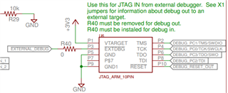
    Have you removed R40? The 10-pin JTAG header is designed to connect to the TM4C1294NCPDT that is on the LaunchPad by default. R40 has to be removed to support external debug:

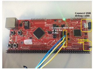
    You do need to remove the 0R resistors as you highlighted. Another way to connect to ICDI would be to use the 14 pin X1 header and manually pull the signals over without a ribbon cable (or you could attach them via blue wire to a ribbon cable if needed).

    That connection process is listed in Section 4.8 of our JTAG User's Guide: https://www.ti.com/lit/pdf/spma075

    In the case where the ICDI and target board are getting damaged, I am using the ICDI interface just to unlock the processor and load a boot loader plus MAC address.  When it fails, the ICDI board itself identifies to LM Flash programmer and can have a firmware update via LM Flash programmer, but it will no longer connect to the target TM4C129 PCB.

    Understood. I have not heard of a situation like this before but this is also the first time I recall helping someone with using the 10-pin JTAG for external debug. I actually hadn't recalled that it was even possible until reviewing the LaunchPad schematic as we don't have it documented in our JTAG guide. I suspect the issue is related to the R40 resistor not being removed.

    If that doesn't resolve the issue however, I would recommend that you move to following the documented process in Section 4.8 of our JTAG guide because that is one that I have helped multiple customers successfully use without any issues of board/device damage. There may be a reason the JTAG header wasn't documented though from a signal standpoint I would anticipate that it should be okay if the R40 resistor is removed properly...

    Best Regards,

    Ralph Jacobi

  • Hello Jacobi

    I believe I now know the reason for the damage and thought I should report just so anyone else reading this has all the information.

    The LMFLASH PROGRAMMER provides the device unlock function.

    This requires the power cycling of the board.

    As the ICDI interface has no switch to allow the power to be cycled, the JTAG connector was being unplugged and then plugged back in.  I think this has caused surges into the device which damaged the JTAG pins.

    I have modified an ICDI to provide a switch to turn the target power OFF and ON and have not had any instances of damage occurring since.

    Regards

    Barry