Part Number: MSP432E401Y
Hi,
Good day. Our customer has an inquiry about the MSP432E4's timer. Kindly see below.
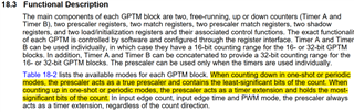
There is a question about MSP432E4's Timer, 16-bits used individually,I can configure Timer2B as TIMER_CFG_B_PERIODIC, and use MAP_TimerLoadSet set the counter to 1000, it may count from 1000 to 0,that's all right
if I change TIMER_CFG_B_PERIODIC by TIMER_CFG_B_PERIODIC_UP it could not work, only 0-65535.
No error encountered. I want count up from 0-load(match)
https://paste.ubuntu.com/p/pYN2Zw4k9T//* --COPYRIGHT--,BSD
* Copyright (c) 2017, Texas Instruments Incorporated
* All rights reserved.
*
* Redistribution and use in source and binary forms, with or without
* modification, are permitted provided that the following conditions
* are met:
*
* * Redistributions of source code must retain the above copyright
* notice, this list of conditions and the following disclaimer.
*
* * Redistributions in binary form must reproduce the above copyright
* notice, this list of conditions and the following disclaimer in the
* documentation and/or other materials provided with the distribution.
*
* * Neither the name of Texas Instruments Incorporated nor the names of
* its contributors may be used to endorse or promote products derived
* from this software without specific prior written permission.
*
* THIS SOFTWARE IS PROVIDED BY THE COPYRIGHT HOLDERS AND CONTRIBUTORS "AS IS"
* AND ANY EXPRESS OR IMPLIED WARRANTIES, INCLUDING, BUT NOT LIMITED TO,
* THE IMPLIED WARRANTIES OF MERCHANTABILITY AND FITNESS FOR A PARTICULAR
* PURPOSE ARE DISCLAIMED. IN NO EVENT SHALL THE COPYRIGHT OWNER OR
* CONTRIBUTORS BE LIABLE FOR ANY DIRECT, INDIRECT, INCIDENTAL, SPECIAL,
* EXEMPLARY, OR CONSEQUENTIAL DAMAGES (INCLUDING, BUT NOT LIMITED TO,
* PROCUREMENT OF SUBSTITUTE GOODS OR SERVICES; LOSS OF USE, DATA, OR PROFITS;
* OR BUSINESS INTERRUPTION) HOWEVER CAUSED AND ON ANY THEORY OF LIABILITY,
* WHETHER IN CONTRACT, STRICT LIABILITY, OR TORT (INCLUDING NEGLIGENCE OR
* OTHERWISE) ARISING IN ANY WAY OUT OF THE USE OF THIS SOFTWARE,
* EVEN IF ADVISED OF THE POSSIBILITY OF SUCH DAMAGE.
* --/COPYRIGHT--*/
/******************************************************************************
* MSP432E4 Example project for Configuring a timer in 16-bit periodic mode
*
* Description: In this example, the timer is configured to generate an
* interrupt every 0.1 sec in 16-bit periodic mode. On the interrupt the state
* of the LED D2
*
* MSP432E401Y
* ------------------
* /|\| |
* | | |
* --|RST |
* | |
* | PN0|-->LED
* | |
* | |
* | |
* Author: Amit Ashara
*******************************************************************************/
/* DriverLib Includes */
#include
/* Standard Includes */
#include
#include
#include "uartstdio.h"
int i=0;
void TIMER2B_IRQHandler(void)
{
uint32_t getTimerInterrupt;
/* Get timer interrupt status and clear the same */
getTimerInterrupt = MAP_TimerIntStatus(TIMER2_BASE, true);
MAP_TimerIntClear(TIMER2_BASE, getTimerInterrupt);
/* Toggle the LED */
if(1)
{
i=0;
MAP_GPIOPinWrite(GPIO_PORTN_BASE, GPIO_PIN_0,
~(MAP_GPIOPinRead(GPIO_PORTN_BASE, GPIO_PIN_0)));
UARTprintf("cnt\r\n");
}
}
void ConfigureUART(uint32_t systemClock)
{
/* Enable the clock to GPIO port A and UART 0 */
MAP_SysCtlPeripheralEnable(SYSCTL_PERIPH_GPIOA);
MAP_SysCtlPeripheralEnable(SYSCTL_PERIPH_UART0);
/* Configure the GPIO Port A for UART 0 */
MAP_GPIOPinConfigure(GPIO_PA0_U0RX);
MAP_GPIOPinConfigure(GPIO_PA1_U0TX);
MAP_GPIOPinTypeUART(GPIO_PORTA_BASE, GPIO_PIN_0 | GPIO_PIN_1);
/* Configure the UART for 115200 bps 8-N-1 format */
UARTStdioConfig(0, 115200, systemClock);
}
int main(void)
{
uint32_t systemClock;
/* Configure the system clock for 120 MHz */
systemClock = MAP_SysCtlClockFreqSet((SYSCTL_XTAL_25MHZ | SYSCTL_OSC_MAIN |
SYSCTL_USE_PLL | SYSCTL_CFG_VCO_480),
120000000);
ConfigureUART(systemClock);
/* Enable the clock to the GPIO Port N and wait for it to be ready */
MAP_SysCtlPeripheralEnable(SYSCTL_PERIPH_GPION);
while(!(SysCtlPeripheralReady(SYSCTL_PERIPH_GPION)))
{
}
/* Configure the GPIO PN0 as output and put in low state */
MAP_GPIOPinTypeGPIOOutput(GPIO_PORTN_BASE, GPIO_PIN_0);
MAP_GPIOPinWrite(GPIO_PORTN_BASE, GPIO_PIN_0, ~(GPIO_PIN_0));
/* Enable the Timer-0 in 16-bit periodic mode with interrupt generated
* every 0.1 sec */
MAP_SysCtlPeripheralEnable(SYSCTL_PERIPH_TIMER2);
while(!(SysCtlPeripheralReady(SYSCTL_PERIPH_TIMER2)))
{
}
MAP_TimerConfigure(TIMER2_BASE, TIMER_CFG_SPLIT_PAIR | TIMER_CFG_B_PERIODIC_UP);/*TIMER_CFG_B_PERIODIC work*/
MAP_TimerIntEnable(TIMER2_BASE, TIMER_TIMB_TIMEOUT);
/* Since the 16-bit timer can count only 65536 value, we use the pre
* scaler of 256 to divide down the count rate by 256. Thus the actual
* count load is 120e6/256 = 468750. Now when to count at 0.1 sec the
* load value in the timer would be 468750 * 0.1 = 46875 = 0xB71B. */
MAP_TimerPrescaleSet(TIMER2_BASE, TIMER_B, 255);
//MAP_TimerLoadSet(TIMER2_BASE, TIMER_B, (systemClock/(256*10)));
// MAP_TimerLoadSet(TIMER2_BASE, TIMER_B, 10000); /*could not work,just count 0-65535*/
// MAP_TimerMatchSet(TIMER2_BASE, TIMER_B, 10000); /*could not work,just count 0-65535*/
//MAP_TimerMatchSet(TIMER2_BASE, TIMER_B, (systemClock/(256*10)));
/* Enable Timer Interrupt */
MAP_IntEnable(INT_TIMER2B);
/* Enable the timer count */
MAP_TimerEnable(TIMER2_BASE, TIMER_B);
UARTprintf("Hello\r\n");
while(1)
{
}
}
Can you please help us? Thank you.
Regards,
Cedrick