This thread has been locked.

If you have a related question, please click the "Ask a related question" button in the top right corner. The newly created question will be automatically linked to this question.

AM2434: GPMC NOR async read setup and hold time

Part Number: AM2434

Dear  TI,

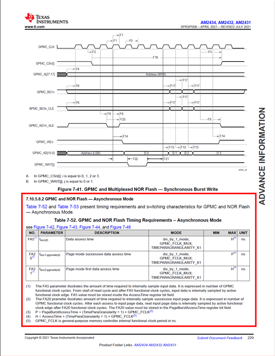
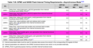
I am using GPMC in 16 bit, non multiplex, NOR asynchronous mode. GPMC CONFIG5.RDACCESSTIME specifies the read sampling point. I cannot find corresponding setup & hold time spec in SPRSP65B data sheet. F12 & F13 rows of Table 7-50 on page 220 contain such spec for NOR sync mode only.

What about my case?

Regards, Kalman

  • Hello Kalman,

    Can you verify you are using the latest release of the datasheet?

    I was able to locate section 7.10.5.8.2) GPMC and NOR Flash - Asynchronous Mode on page 229.

    www.ti.com/.../am2434

    Regards,

  • Hello Fleenor,

    yes I am using the same data sheet (SPRSP65B – APRIL 2021 – REVISED JULY 2021) and have found this table. FA20 & FA21 deal with burst mode timing. FA5 is the internal sampling time of data bus at read cycles set in CONFIG5.RDACCESSTIME. Where is input data setup & hold time specification for asynchronous mode? My question is still open.

    Regards, Kalman

  • Apologies for the misunderstanding. I have reached out to our GPMC expert and will provide additional feedback before the end of the week.

  • Hi Fleenor,

    have you found some nanosecs for me?

    Regards, Kalman

  • Hello Kalman,

    Thanks for your patience in this matter. After connecting with the GPMC expert, we have come to the following conclusions regarding data setup and hold times for asynchronous operation:

    • GPMC_FCLK is internal only and used as reference for the setup and hold time requirements.
    • This signal cannot be brought outside the device and the customer/tester cannot probe the reference clock and validate a relative setup and hold time.
    • Synchronous mode allows us to use the clock to latch the data output to a pin where we can measure both signals.
    • At some point it may have been assumed that the GPMC cycle would be so slow that setup and hold times were easily met.
    • Recent requirements are driving additional development efforts in regards to GPMC usability. This could contribute to more thorough examples and test cases to better define these internal timing characteristics. However, there are no additional parameters defined in the datasheet at this time.

    Update: Adding direct feedback from GPMC expert:


    Previous Datasheets published  below "Internal Timing Requirements" Table.

    Using this table, timing analysis is taken inside the device instead of at the pins of the device. It’s got the max delays (for AM335x) from OEn internal generation by GPMC_FCLK to its pin and "input data capture from internal GPMC_FCLK". Not really a setup/hold time but in theory you could approximate a setup and hold time with this information.


    We took this table out of the datasheets with the first RIOT because a customer cannot measure this internal GPMC_FCLK to reproduce the timing.

    When we took out this table, we should have added a new requirement that we can measure on the pins like OEn pin low to data pins setup, and OEn pin high to data pins hold. Since internal clock is launching OEn and latching data, I think the measurement should include the output delay from OEn generation by internal GPMC_FCLK through the output buffer to the pin, and also include the input delay through the data buffers. I'm told the 16FF process has a wide range of IO delays that vary with PVT and ageing so we'd have to publish the worst maximum, which might be 10-20ns, we'll see. I will ask Howard if any other peripheral has similar IO delay data published.


    I have little concern about the ability to meet setup and hold times since there is a programmable number of FCLK cycles from OEn low to ReadAccessTime, and again from ReadAccessTime to OEn high. OEn signals the memory/FPGA to drive data on the bus. Until we can find a number and a way to express it, the customer should find a value that works and pad it on both ends by 1 or 2 FCLK cycles for margin, limiting peak performance.


    The variation in delay through buffers is the reason for the pad loopback clocks which use a latching clock that has traveled through an output buffer and back into an input buffer, so it is delayed by the same amount as the OEn output and data input. We have this PLB clock with GPMC when in synchronous mode.


    If you have additional questions please follow up on this thread.

    Thanks and Regards,

    Zack Fleenor

  • Hello Fleenor & Zack,

    thanks for your detailed answer.

    Internal sampling happens at ReadAccessTime. If  the internal setup & hold time wold be known then considering the pad delays the external setup/hold time could be estimated.

    Regards, Kalman

  • Hello Kalman,

    Thank you for your patience. This issue is still under discussion with our Static Timing Analysis team and GPMC experts. It may be some time still before we can come back with solid numbers for these parameters.

    Best Regards,

    Zackary Fleenor