This thread has been locked.

If you have a related question, please click the "Ask a related question" button in the top right corner. The newly created question will be automatically linked to this question.

TM4C129XNCZAD: Configuring SSI module for SPI communication with two slave devices

Part Number: TM4C129XNCZAD

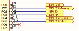
Hello, I want to use SPI communication to communicate between TM4C129XNCZAD and two other devices. I am having trouble understanding how to configure the SSI Module to achieve this. Here is the code I have and the PIN map for the SPI connections.

    //enable the pins used for SPI communication.
    SysCtlPeripheralEnable(SYSCTL_PERIPH_GPIOQ);
    GPIOPinConfigure(GPIO_PQ0_SSI3CLK);
    GPIOPinConfigure(GPIO_PQ1_SSI3FSS);
    GPIOPinConfigure(GPIO_PQ2_SSI3XDAT0);
    GPIOPinTypeSSI(PQ_SPI_PORT, (   PQ0_SPI_CLK_PIN         |
                                    PQ1_SPI_SS_MEMORY_PIN   |
                                    PQ2_SPI_TX_PIN          ));


    //
    // Enable the SSI0 peripheral
    //
    SysCtlPeripheralEnable(SYSCTL_PERIPH_SSI3);

    // Wait for the SSI0 module to be ready.
    //
    while(!SysCtlPeripheralReady(SYSCTL_PERIPH_SSI3))
    {
    }

    //
    // Configure the SSI.
    //
    SSIConfigSetExpClk(SSI3_BASE, SysCtlClockFreqSet((SYSCTL_OSC_INT | SYSCTL_USE_OSC), 50000000), SSI_FRF_MOTO_MODE_0, SSI_MODE_MASTER, 2000000, 8);

    //
    //Enable the SSI module
    //
    SSIEnable(SSI3_BASE);

Digital Potentiometer (Digi Pot) and Digital to Analog Converter (DAC) are the two devices I want to communicate with and I was assuming I need to just configure two SSI<n> but I am not sure how to do this considering both of them are on the same PORT. Can someone give me an example or some help on how to configure SSI peripheral to Communicate with these two devices as slaves and TM4C as master?

  • Hello Omer,

    To communicate with multiple slave devices, you need a dedicated SS line for each of them. Most customers opt to not configure the SS line in the SSI peripheral directly but instead control it as a GPIO. This way you can control which SS lines you are toggling in all situations whether there are one or more devices on the SSI bus.

    So effectively what you will do is:

    1. Configure SSI as you have, but omit the FSS pin from the SSI configuration
    2. Configure Pins PQ1, PQ4, and PQ5 as GPIO that are digital outputs and set them to correct signal to not select the device - most devices are low true SS so you'd set them to be high and that will be my assumption moving forward with these steps.
    3. When communicating with a specific device, start by setting that I/O low (if SS is low true), and then issue your SSI read/write commands.
    4. Once communication is done with that device, re-assert the high.

    I would also recommend you make dedicated functions for each of those so they happen in sequence and you don't risk having a different SS line still pulled down.

    Hopefully this flow makes sense for you!

    Best Regards,

    Ralph Jacobi

  • Thanks for the advice, I was thinking of just doing the whole thing as GPIO pin read/writes did not occur to me to do it this way and this sounds way easier. Thumbsup