This thread has been locked.

If you have a related question, please click the "Ask a related question" button in the top right corner. The newly created question will be automatically linked to this question.

TM4C129ENCZAD: Waiting for Link

Part Number: TM4C129ENCZAD
Other Parts Discussed in Thread: EK-TM4C1294XL,

I have a custom PCB with a TM4C129ENCZADT3 MCU that I am trying to get the enet_uip example for the EK-TM4C1294XL launchpad board to work with the TM4C129ENCZADT3 MCU.

I start by testing the enet_uip example project on the EK-TM4C1294XL to check that it is working correctly. In order to get this project working on the custom board I had to uncomment,

#define USE_STATIC_IP

To set a static ip address on the launchpad and the custom board.

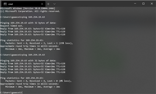
My PC has a static ip of 169.254.19.62, and the EK-TM4C1294XL has a static ip of 169.254.19.63. After programming the EK-TM4C1294XL I can send ping requests to the launchpad and can see packets being sent back to the PC.

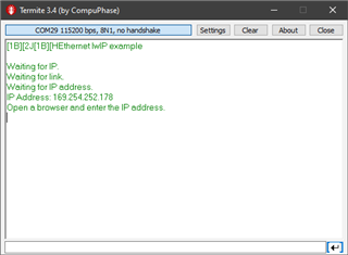
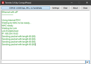
Below is debug output from the launchpad. Packets are being sent in response to a ping request.

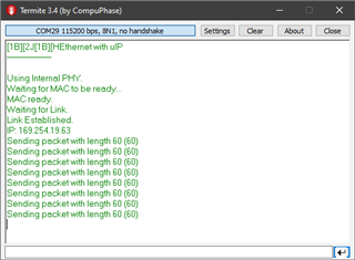
Below is the PC sending packets to the launchpad,

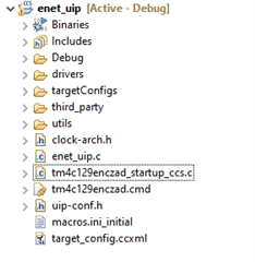
I attempt the change the example enet_uip project to work with the custom PCB that has a TM4C129ENCZADT3 MCU.

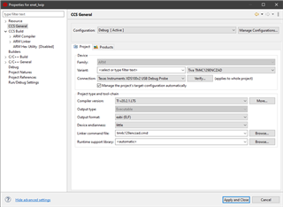
I first go to the project properties and change the Device and Connection:

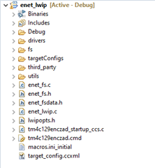
After clicking apply and close CCS seems to add a new linker command file, and startup source file.

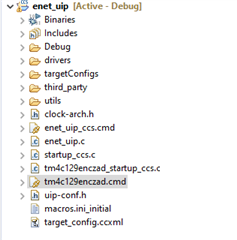
I modified tm4c129enczad_startup_ccs.c so that it matches startup_ccs.c and modified tm4c129enczad.cmd so that it matches enet_uip_ccs.cmd. After changing these files, the old files from the example project are removed.

A MAC address is programmed into the custom PCB successfully.

CORTEX_M4_0: GEL Output: 
Memory Map Initialization Complete
CORTEX_M4_0: User Register operation...
CORTEX_M4_0: Writing the following value to Register0 (9a9413) and Register1 (2af7e2) translated from the given MAC address
CORTEX_M4_0: Programmed value committing to User Register 0
CORTEX_M4_0: Programmed value was committed to User Register 0
CORTEX_M4_0: Programmed value committing to User Register 1
CORTEX_M4_0: Programmed value was committed to User Register 1
CORTEX_M4_0: Operation completed successfully.
CORTEX_M4_0: User Register operation...
CORTEX_M4_0: MAC address value: 13-94-9a-e2-f7-2a
CORTEX_M4_0: Operation completed successfully.

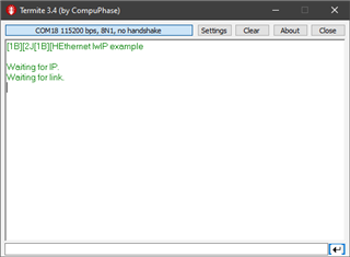
After programming the custom pcb I can not get a link to be established. The program sits at Waiting for Link.

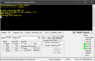
I am not sure if this is a software or hardware problem. I have tried multiple ethernet switches and CAT5e cables with no success. Schematics and gerber files are attached for the custom PCB. Does anyone have any suggestions?

Thanks,

Allan

MCU_Sch.pdf

Gerbs.zip

  • HI Allan,

      Some comments:

      - On your schematic, I'm unable to find how the RBIAS pin is connected? It must be connected to GND via a 4.87kohm resistor. Please refer to the datasheet or the LaunchPad board schematic. If RBIAS pin is missing correct connection then it is pretty much the reason for the problem. 

      - The chip on the LaunchPad is a PGE package while you have ZAD package. Therefore, you cannot use directly the code for the LauchPad on your custom board. There is probably no difference on the Ethernet differential pins like EN0TX0_P and EN0TX0_N. But for the Ethernet LED pins the pinmux will be different. 

      - I will suggest you first run another Ethernet example such as enet_lwip on both the LP board and your custom board. Prove again that you still get the same result - the LP works but not your custom board. 

      - I will also suggest you look at the Ethernet examples for the DK EVM board, not the EK LP board. The MCU on DK EVM board is of ZAD package. These examples have code to display on the LCD. You will need to remove the LCD code. Or at least go through the examples on how the pinmuxing is done on the DK board vs. EK board , 


  • Looks like I missed the 4.87kohm resistor you already have on the schematic but please check other items I suggested. 

  • Hi Charles,

    The enet_lwip example is working on the launchpad. The LP is able to obtain a link and get an ip address,

    Going through the same procedure to test the enet_lwip example on the custom board. I first change the device to TM4C129ENCZAD and modify the debugger connection,

    Copying startup_ccs.c to tm4c129enczad_startup_ccs.c and enet_lwip_ccs.cmd to tm4c129enczad.cmd. Then deleting startup_ccs.c and enet_lwip_ccs.cmd.

    The custom board with the enet_lwip example also gets stuck at waiting for link.

    Unfortunately, I don’t have a DK-TM4C129X development kit to verify that the example is working. I have attached the example project I used to program the custom board. I modified enet_uip.c by uncommenting,

    #define USE_STATIC_IP

    To get a static ip address.

    Modified the UpdateStatus function to remove the LCD screen functionality,

    void
    UpdateStatus(char *pcStatus)
    {
        tRectangle sRect;
    
        //
        // Dump that status string to the serial port.
        //
        UARTprintf("%s\n", pcStatus);
    
    //    //
    //    // Clear any previous status message.
    //    //
    //    sRect.i16XMin = 0;
    //    sRect.i16XMax = GrContextDpyWidthGet(&g_sContext) - 1;
    //    sRect.i16YMin = STATUS_Y - 16;
    //    sRect.i16YMax = STATUS_Y + 16;
    //    GrContextForegroundSet(&g_sContext, ClrBlack);
    //    GrRectFill(&g_sContext, &sRect);
    //
    //    //
    //    // Display the new status string.
    //    //
    //    GrContextFontSet(&g_sContext, g_psFontCmss20);
    //    GrContextForegroundSet(&g_sContext, ClrWhite);
    //    GrStringDrawCentered(&g_sContext, pcStatus, -1,
    //                         GrContextDpyWidthGet(&g_sContext) / 2, STATUS_Y, 0);
    }

    I also modified pinout.c to remove SSI0, USB, speaker output, I2C, push button, touch screen, and SPI flash functionality,

    //*****************************************************************************
    //
    // pinout.c - Function to configure the device pins on the DK-TM4C129X.
    //
    // Copyright (c) 2013-2020 Texas Instruments Incorporated.  All rights reserved.
    // Software License Agreement
    // 
    // Texas Instruments (TI) is supplying this software for use solely and
    // exclusively on TI's microcontroller products. The software is owned by
    // TI and/or its suppliers, and is protected under applicable copyright
    // laws. You may not combine this software with "viral" open-source
    // software in order to form a larger program.
    // 
    // THIS SOFTWARE IS PROVIDED "AS IS" AND WITH ALL FAULTS.
    // NO WARRANTIES, WHETHER EXPRESS, IMPLIED OR STATUTORY, INCLUDING, BUT
    // NOT LIMITED TO, IMPLIED WARRANTIES OF MERCHANTABILITY AND FITNESS FOR
    // A PARTICULAR PURPOSE APPLY TO THIS SOFTWARE. TI SHALL NOT, UNDER ANY
    // CIRCUMSTANCES, BE LIABLE FOR SPECIAL, INCIDENTAL, OR CONSEQUENTIAL
    // DAMAGES, FOR ANY REASON WHATSOEVER.
    // 
    // This is part of revision 2.2.0.295 of the DK-TM4C129X Firmware Package.
    //
    //*****************************************************************************
    
    #include <stdbool.h>
    #include <stdint.h>
    #include "inc/hw_gpio.h"
    #include "inc/hw_memmap.h"
    #include "inc/hw_types.h"
    #include "driverlib/gpio.h"
    #include "driverlib/pin_map.h"
    #include "driverlib/rom.h"
    #include "driverlib/sysctl.h"
    #include "drivers/pinout.h"
    
    //*****************************************************************************
    //
    //! \addtogroup pinout_api
    //! @{
    //
    //*****************************************************************************
    
    //*****************************************************************************
    //
    //! Configures the device pins for the standard usages on the DK-TM4C129X.
    //!
    //! This function enables the GPIO modules and configures the device pins for
    //! the default, standard usages on the DK-TM4C129X.  Applications that require
    //! alternate configurations of the device pins can either not call this
    //! function and take full responsibility for configuring all the device pins,
    //! or can reconfigure the required device pins after calling this function.
    //!
    //! \return None.
    //
    //*****************************************************************************
    void
    PinoutSet(void)
    {
        //
        // Enable all the GPIO peripherals.
        //
        ROM_SysCtlPeripheralEnable(SYSCTL_PERIPH_GPIOA);
        ROM_SysCtlPeripheralEnable(SYSCTL_PERIPH_GPIOB);
        ROM_SysCtlPeripheralEnable(SYSCTL_PERIPH_GPIOC);
        ROM_SysCtlPeripheralEnable(SYSCTL_PERIPH_GPIOD);
        ROM_SysCtlPeripheralEnable(SYSCTL_PERIPH_GPIOE);
        ROM_SysCtlPeripheralEnable(SYSCTL_PERIPH_GPIOF);
        ROM_SysCtlPeripheralEnable(SYSCTL_PERIPH_GPIOG);
        ROM_SysCtlPeripheralEnable(SYSCTL_PERIPH_GPIOH);
        ROM_SysCtlPeripheralEnable(SYSCTL_PERIPH_GPIOJ);
        ROM_SysCtlPeripheralEnable(SYSCTL_PERIPH_GPIOK);
        ROM_SysCtlPeripheralEnable(SYSCTL_PERIPH_GPIOL);
        ROM_SysCtlPeripheralEnable(SYSCTL_PERIPH_GPIOM);
        ROM_SysCtlPeripheralEnable(SYSCTL_PERIPH_GPION);
        ROM_SysCtlPeripheralEnable(SYSCTL_PERIPH_GPIOP);
        ROM_SysCtlPeripheralEnable(SYSCTL_PERIPH_GPIOQ);
        ROM_SysCtlPeripheralEnable(SYSCTL_PERIPH_GPIOR);
        ROM_SysCtlPeripheralEnable(SYSCTL_PERIPH_GPIOS);
        ROM_SysCtlPeripheralEnable(SYSCTL_PERIPH_GPIOT);
    
        //
        // PA0-1 are used for UART0.
        //
        ROM_GPIOPinConfigure(GPIO_PA0_U0RX);
        ROM_GPIOPinConfigure(GPIO_PA1_U0TX);
        ROM_GPIOPinTypeUART(GPIO_PORTA_BASE, GPIO_PIN_0 | GPIO_PIN_1);
    
        //
        // PA2-5 are used for SSI0 to the second booster pack.
        //
    //    ROM_GPIOPinConfigure(GPIO_PA2_SSI0CLK);
    //    ROM_GPIOPinConfigure(GPIO_PA3_SSI0FSS);
    //    ROM_GPIOPinConfigure(GPIO_PA4_SSI0XDAT0);
    //    ROM_GPIOPinConfigure(GPIO_PA5_SSI0XDAT1);
    
        //
        // PB0-1/PD6-7/PL6-7 are used for USB.
        //
    //    HWREG(GPIO_PORTD_BASE + GPIO_O_LOCK) = GPIO_LOCK_KEY;
    //    HWREG(GPIO_PORTD_BASE + GPIO_O_CR) = 0xff;
    //    ROM_GPIOPinConfigure(GPIO_PD6_USB0EPEN);
    //    ROM_GPIOPinConfigure(GPIO_PD7_USB0PFLT);
    //    ROM_GPIOPinTypeUSBAnalog(GPIO_PORTB_BASE, GPIO_PIN_0 | GPIO_PIN_1);
    //    ROM_GPIOPinTypeUSBDigital(GPIO_PORTD_BASE, GPIO_PIN_6 | GPIO_PIN_7);
    //    ROM_GPIOPinTypeUSBAnalog(GPIO_PORTL_BASE, GPIO_PIN_6 | GPIO_PIN_7);
    
        //
        // PB2/PD4 are used for the speaker output.
        //
    //    ROM_GPIOPinConfigure(GPIO_PB2_T5CCP0);
    //    ROM_GPIOPinTypeTimer(GPIO_PORTB_BASE, GPIO_PIN_2);
    //    ROM_GPIOPinTypeGPIOOutput(GPIO_PORTD_BASE, GPIO_PIN_4);
    //    ROM_GPIOPinWrite(GPIO_PORTD_BASE, GPIO_PIN_4, 0);
    
        //
        // PB6-7 are used for I2C to the TMP100 and the EM connector.
        //
    //    ROM_GPIOPinConfigure(GPIO_PB6_I2C6SCL);
    //    ROM_GPIOPinConfigure(GPIO_PB7_I2C6SDA);
    //    ROM_GPIOPinTypeI2CSCL(GPIO_PORTB_BASE, GPIO_PIN_6);
    //    ROM_GPIOPinTypeI2C(GPIO_PORTB_BASE, GPIO_PIN_7);
    
        //
        // PE5/PN3/PP1 are used for the push buttons.
        //
    //    ROM_GPIOPinTypeGPIOInput(GPIO_PORTE_BASE, GPIO_PIN_5);
    //    ROM_GPIOPinTypeGPIOInput(GPIO_PORTN_BASE, GPIO_PIN_3);
    //    ROM_GPIOPinTypeGPIOInput(GPIO_PORTP_BASE, GPIO_PIN_1);
    
        //
        // PE7/PP7/PT2-3 are used for the touch screen.
        //
    //    HWREG(GPIO_PORTE_BASE + GPIO_O_LOCK) = GPIO_LOCK_KEY;
    //    HWREG(GPIO_PORTE_BASE + GPIO_O_CR) = 0xff;
    //    ROM_GPIOPinTypeGPIOInput(GPIO_PORTE_BASE, GPIO_PIN_7);
    //    ROM_GPIOPinTypeGPIOInput(GPIO_PORTP_BASE, GPIO_PIN_7);
    //    ROM_GPIOPinTypeGPIOInput(GPIO_PORTT_BASE, GPIO_PIN_2 | GPIO_PIN_3);
    //    ROM_GPIOPinTypeGPIOOutput(GPIO_PORTE_BASE, GPIO_PIN_7);
    //    ROM_GPIOPinWrite(GPIO_PORTE_BASE, GPIO_PIN_7, 0);
    //    ROM_GPIOPinTypeGPIOOutput(GPIO_PORTP_BASE, GPIO_PIN_7);
    //    ROM_GPIOPinWrite(GPIO_PORTP_BASE, GPIO_PIN_7, 0);
    //    ROM_GPIOPinTypeGPIOOutput(GPIO_PORTT_BASE, GPIO_PIN_2 | GPIO_PIN_3);
    //    ROM_GPIOPinWrite(GPIO_PORTT_BASE, GPIO_PIN_2 | GPIO_PIN_3, 0);
    
        //
        // PF0/PF4-5/PH4/PQ0-2 are used for the SPI flash (on-board and SD card).
        // PH4 selects the SD card and PQ1 selects the on-board SPI flash.
        //
    //    ROM_GPIOPinConfigure(GPIO_PF0_SSI3XDAT1);
    //    ROM_GPIOPinConfigure(GPIO_PF4_SSI3XDAT2);
    //    ROM_GPIOPinConfigure(GPIO_PF5_SSI3XDAT3);
    //    ROM_GPIOPinConfigure(GPIO_PQ0_SSI3CLK);
    //    ROM_GPIOPinConfigure(GPIO_PQ2_SSI3XDAT0);
    //    ROM_GPIOPinTypeSSI(GPIO_PORTF_BASE, GPIO_PIN_0 | GPIO_PIN_4 | GPIO_PIN_5);
    //    ROM_GPIOPinTypeGPIOOutput(GPIO_PORTH_BASE, GPIO_PIN_4);
    //    ROM_GPIOPinWrite(GPIO_PORTH_BASE, GPIO_PIN_4, GPIO_PIN_4);
    //    ROM_GPIOPinTypeSSI(GPIO_PORTQ_BASE, GPIO_PIN_0 | GPIO_PIN_2);
    //    ROM_GPIOPinTypeGPIOOutput(GPIO_PORTQ_BASE, GPIO_PIN_1);
    //    ROM_GPIOPinWrite(GPIO_PORTQ_BASE, GPIO_PIN_1, GPIO_PIN_1);
    
        //
        // PF1/PK4/PK6 are used for Ethernet LEDs.
        //
        ROM_GPIOPinConfigure(GPIO_PF1_EN0LED2);
    //    ROM_GPIOPinConfigure(GPIO_PK4_EN0LED0);
    //    ROM_GPIOPinConfigure(GPIO_PK6_EN0LED1);
        GPIOPinTypeEthernetLED(GPIO_PORTF_BASE, GPIO_PIN_1);
    //    GPIOPinTypeEthernetLED(GPIO_PORTK_BASE, GPIO_PIN_4);
    //    GPIOPinTypeEthernetLED(GPIO_PORTK_BASE, GPIO_PIN_6);
    
        //
        // PF6-7/PJ6/PS4-5/PR0-7 are used for the LCD.
        //
    //    ROM_GPIOPinConfigure(GPIO_PF7_LCDDATA02);
    //    ROM_GPIOPinConfigure(GPIO_PJ6_LCDAC);
    //    ROM_GPIOPinConfigure(GPIO_PR0_LCDCP);
    //    ROM_GPIOPinConfigure(GPIO_PR1_LCDFP);
    //    ROM_GPIOPinConfigure(GPIO_PR2_LCDLP);
    //    ROM_GPIOPinConfigure(GPIO_PR3_LCDDATA03);
    //    ROM_GPIOPinConfigure(GPIO_PR4_LCDDATA00);
    //    ROM_GPIOPinConfigure(GPIO_PR5_LCDDATA01);
    //    ROM_GPIOPinConfigure(GPIO_PR6_LCDDATA04);
    //    ROM_GPIOPinConfigure(GPIO_PR7_LCDDATA05);
    //    ROM_GPIOPinConfigure(GPIO_PS4_LCDDATA06);
    //    ROM_GPIOPinConfigure(GPIO_PS5_LCDDATA07);
    //    ROM_GPIOPinTypeGPIOOutput(GPIO_PORTF_BASE, GPIO_PIN_6);
    //    ROM_GPIOPinWrite(GPIO_PORTF_BASE, GPIO_PIN_6, GPIO_PIN_6);
    //    GPIOPinTypeLCD(GPIO_PORTF_BASE, GPIO_PIN_7);
    //    GPIOPinTypeLCD(GPIO_PORTJ_BASE, GPIO_PIN_6);
    //    GPIOPinTypeLCD(GPIO_PORTR_BASE,
    //                       (GPIO_PIN_0 | GPIO_PIN_1 | GPIO_PIN_2 | GPIO_PIN_3 |
    //                        GPIO_PIN_4 | GPIO_PIN_5 | GPIO_PIN_6 | GPIO_PIN_7));
    //    GPIOPinTypeLCD(GPIO_PORTS_BASE, GPIO_PIN_4 | GPIO_PIN_5);
    
        //
        // PQ7 is used for the user LED.
        //
    //    ROM_GPIOPinTypeGPIOOutput(GPIO_PORTQ_BASE, GPIO_PIN_7);
    //    ROM_GPIOPinWrite(GPIO_PORTQ_BASE, GPIO_PIN_7, 0);
    }
    
    //*****************************************************************************
    //
    //! Configures the USB pins for ULPI connection to an external USB PHY.
    //!
    //! This function configures the USB ULPI pins to connect the DK-TM4C129X board
    //! to an external USB PHY in ULPI mode.  This allows the external PHY to act
    //! as an external high-speed phy for the DK-TM4C129X.  This function must be
    //! called after the call to PinoutSet() to properly configure the pins.
    //!
    //! \return None.
    //
    //*****************************************************************************
    #ifdef USE_ULPI
    void
    USBULPIPinoutSet(void)
    {
        //
        // Enable all the peripherals that are used by the ULPI interface.
        //
        ROM_SysCtlPeripheralEnable(SYSCTL_PERIPH_GPIOB);
        ROM_SysCtlPeripheralEnable(SYSCTL_PERIPH_GPIOL);
        ROM_SysCtlPeripheralEnable(SYSCTL_PERIPH_GPIOM);
        ROM_SysCtlPeripheralEnable(SYSCTL_PERIPH_GPIOP);
    
        //
        // ULPI Port B pins.
        //
        ROM_GPIOPinConfigure(GPIO_PB2_USB0STP);
        ROM_GPIOPinConfigure(GPIO_PB3_USB0CLK);
        ROM_GPIOPinTypeUSBDigital(GPIO_PORTB_BASE, GPIO_PIN_2 | GPIO_PIN_3);
        GPIOPadConfigSet(GPIO_PORTB_BASE, GPIO_PIN_2 | GPIO_PIN_3,
                         GPIO_STRENGTH_12MA, GPIO_PIN_TYPE_STD);
    
        //
        // ULPI Port P pins.
        //
        ROM_GPIOPinConfigure(GPIO_PP2_USB0NXT);
        ROM_GPIOPinConfigure(GPIO_PP3_USB0DIR);
        ROM_GPIOPinConfigure(GPIO_PP4_USB0D7);
        ROM_GPIOPinConfigure(GPIO_PP5_USB0D6);
        ROM_GPIOPinTypeUSBDigital(GPIO_PORTP_BASE, GPIO_PIN_2 | GPIO_PIN_3 |
                                                   GPIO_PIN_4 | GPIO_PIN_5);
        GPIOPadConfigSet(GPIO_PORTP_BASE,
                         GPIO_PIN_2 | GPIO_PIN_3 | GPIO_PIN_4 | GPIO_PIN_5,
                         GPIO_STRENGTH_12MA, GPIO_PIN_TYPE_STD);
    
        //
        // ULPI Port L pins.
        //
        ROM_GPIOPinConfigure(GPIO_PL5_USB0D5);
        ROM_GPIOPinConfigure(GPIO_PL4_USB0D4);
        ROM_GPIOPinConfigure(GPIO_PL3_USB0D3);
        ROM_GPIOPinConfigure(GPIO_PL2_USB0D2);
        ROM_GPIOPinConfigure(GPIO_PL1_USB0D1);
        ROM_GPIOPinConfigure(GPIO_PL0_USB0D0);
        ROM_GPIOPinTypeUSBDigital(GPIO_PORTL_BASE, GPIO_PIN_0 | GPIO_PIN_1 |
                                                   GPIO_PIN_2 | GPIO_PIN_3 |
                                                   GPIO_PIN_4 | GPIO_PIN_5);
        GPIOPadConfigSet(GPIO_PORTL_BASE,
                         GPIO_PIN_0 | GPIO_PIN_1 | GPIO_PIN_2 | GPIO_PIN_3 |
                         GPIO_PIN_4 | GPIO_PIN_5,
                         GPIO_STRENGTH_12MA, GPIO_PIN_TYPE_STD);
        //
        // ULPI Port M pins used to control the external USB oscillator and the
        // external USB phy on the DK-TM4C129X-DPHY board.
        //
        // PM1 - Enables the USB oscillator on the DK-TM4C129X-DPHY board.
        // PM3 - Enables the USB phy on the DK-TM4C129X-DPHY board.
        //
        ROM_GPIOPinTypeGPIOOutput(GPIO_PORTM_BASE, GPIO_PIN_1 | GPIO_PIN_3);
        ROM_GPIOPinWrite(GPIO_PORTM_BASE, GPIO_PIN_1 | GPIO_PIN_3, GPIO_PIN_1 |
                                                                   GPIO_PIN_3);
    }
    #endif
    
    //*****************************************************************************
    //
    // Close the Doxygen group.
    //! @}
    //
    //*****************************************************************************
    

    Do you think there might be a problem with the differential trace impedance?

    Thanks,

    Allan

    enet_lwip_example.zip

  • Hi Charles,

    It turns out that the board house swapped R44 and C7. Unswapping these components fixed the issue! 

    I can get a link and ping the custom board!

    Thanks for your help.

    Allan