This thread has been locked.

If you have a related question, please click the "Ask a related question" button in the top right corner. The newly created question will be automatically linked to this question.

LP-AM243: LP AM243x can not flash firmware

Part Number: LP-AM243


Hello TI support team.

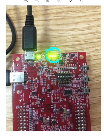
I just received new LP-243x board.

I start to check for normal working board.

But it seem i can not download firmware into Am243x IC.

Can you help me some advise.

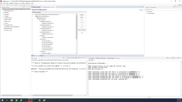
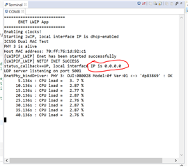
Below is the status of my working:

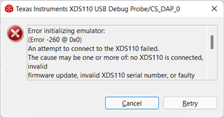
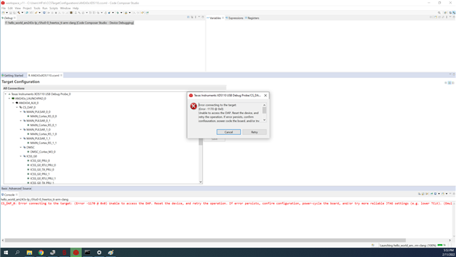
CS_DAP_0: Error initializing emulator: (Error -260 @ 0x0) An attempt to connect to the XDS110 failed. The cause may be one or more of: no XDS110 is connected, invalid firmware update, invalid XDS110 serial number, or faulty USB cable. The firmware and serial number may be updated using the xdsdfu utility found in the .../ccs_base/common/uscif/xds110 directory of your installation. View the XDS110SupportReadMe.pdf file there for instructions. (Emulation package 9.6.0.00172)

  • Hi Duong,

    Looks like you have set the boot mode to QSPI which is not the boot mode for flashing the initial binary (SBL_NULL) into the on board QSPI flash. Please refer to the following URL: https://software-dl.ti.com/mcu-plus-sdk/esd/AM243X/08_01_00_36/exports/docs/api_guide_am243x/EVM_SETUP_PAGE.html#EVM_FLASH_SOC_INIT

    You will need to download and install the MCU+ SDK 08.01.00.36 from: https://www.ti.com/tool/download/MCU-PLUS-SDK-AM243X

    Best regards,

    Ming

  • Hello Mr Ming Wei,

    Today i check the guide that link you sent to me.

    Almost is done but i can not flash sw to LP-AM243x board.

    Download fail and have the same result with both UART mode and QSPI mode.

    What is the mode to flash sw to LP-AM243z. As i know it is QSPI mode, right?

    Can you help me for some advise.

    Here are my process:

    1. Cable Connections: ok

    2. Setup UART Terminal: ok

    3. Flash SOC Initialization Binary: ok

    -->But flash SW to LP-AM243x still fail as text below

    "CS_DAP_0: Error connecting to the target: (Error -1170 @ 0x0) Unable to access the DAP. Reset the device, and retry the operation. If error persists, confirm configuration, power-cycle the board, and/or try more reliable JTAG settings (e.g. lower TCLK). (Emulation package 9.6.0.00172)"

    "Unable to connect to the target"

    -->Fail the same with both  boot mode config: UART and OSPI

    QSPI Mode                                                                                                                            UART Mode 


  • Hi Duong,

    Looks like you have flashed the initial SBL_NULL to the flash successfully.

    After that, switch to OSPI boot mode, then connect UART. You should see the following display on UART output:

    Once you see the correct UART display, then you can launch the AM243xXDS110.ccxml and connect to the R5_0_0 core. The paused address should be either 0x44 or 0x00, then you are ready to load your application code (like HelloWorld).

    Bestregards,

    Ming  

  • Hello Mr Ming Wei,

    How can i setup paused addred to 0x44 or 0x00.

    Pleade guide me, it is the first time i work with CCS and TI chip 

    thanks,

  • Hi Duong,

    Refer to AM243x MCU+ SDK: CCS Launch, Load and Run (ti.com) for how to get to 0x44 or 0x00 for R5_0_0 in CCS.

    Best regards,

    Ming

  • Hello Mr Ming Wei,

    Thank you so much for this time.

    It very helpful with me, i can flash for chip.

    Today i check the ethernet sample with the link on Resource Explorer:

    lwip:

          - enet_lwip_CPSW

          - enet_lwip_ICSSG

    They run well but i saw that the IP is always are: 0.0.0.0

    Here is the guide line from e2e.ti.com: software-dl.ti.com/.../EXAMPLES_LWIP_ENET.html

    • If you see a valid, non-zero MAC address but IP address is 0.0.0.0 then
      • Make sure you see link_callback==UP message, if not check the ethernet cable
      • Check the local network and check if the DHCP server is indeed running as expected
      • When using a home broadband/wifi router, its possible to check the clients connected to the DHCP server via a web browser. Check your router user manual for more details.

    -> You can see above image: "link_callback==UP"

    -> DHCP server  is OK via check gate way by web browser: http://192.168.1.1/

    -> LAN Cable is OK 

    ->I also double check the IP range and LAN connection. every thing is ok.

    Can you explain for me: why ip always 0.0.0.0 instead 192.x.x.x

    I am sorry because i just start with program firmware for TI IC.

    thanks and best regards,

  • Hi Duong,

    Since the original thread is resolved, I would like to suggest you close this thread and create another thread for the LWIP_enet example issue. This will help us to assign the right expert to resolve your question in a timely manner. Thanks!

    Best regards,

    Ming