Part Number: TM4C129XNCZAD
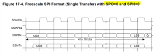
Hello, I have a custom board with the above uC and I need to use it to communicate with DACx0508. I saw that built in SSI module only allows for up to 16 bits of data transfer at a time however DAC requires 24 bits of data. I was hoping doing two calls to the peripheral function SSIDataPut() with 12 bits of data each time would do the trick but no such luck. I am assuming it is not working because there is something wrong with the SSI initialization and not because of the DAC. The way I am testing is checking the voltage after disabling the internal 2.5V reference of the DAC and seeing if the voltage changes to 3V. Here is the schematics and my code.
SSI module initialization with setting DAC internal reference off at the end:
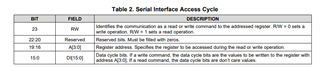
Note: the address 0x3 represents the configuration register of DAC and the data 0x0100 sets the configuration to turn off the internal reference. 0 at bit 23 specifies this is a write.
    //enable the pins used for SPI communication.
    SysCtlPeripheralEnable(SYSCTL_PERIPH_GPIOQ);

    while(!SysCtlPeripheralReady(SYSCTL_PERIPH_GPIOQ)){

    }
    //
    // Configure the SS pin and communication pins as GPIO output pins.
    //
    GPIOPinTypeGPIOOutput(PQ_SPI_PORT, (PQ1_SPI_SS_MEMORY_PIN       |
                                        PQ4_SPI_SS_DIGIPOT_PIN      |
                                        PQ5_SPI_SS_DAC_PIN));

    //
    // Enable the SSI3 peripheral
    //
    SysCtlPeripheralEnable(SYSCTL_PERIPH_SSI3);

    while(!SysCtlPeripheralReady(SYSCTL_PERIPH_SSI3)){

    }

    GPIOPinTypeSSI(PQ_SPI_PORT, (   PQ0_SPI_CLK_PIN         |
                                    PQ2_SPI_TX_PIN          |
                                    PQ3_SPI_RX_PIN));

    GPIOPinConfigure(GPIO_PQ0_SSI3CLK);
    GPIOPinConfigure(GPIO_PQ2_SSI3XDAT0);
    GPIOPinConfigure(GPIO_PQ3_SSI3XDAT1);

    // Wait for the SSI3 module to be ready.
    //
    while(!SysCtlPeripheralReady(SYSCTL_PERIPH_SSI3))
    {
    }

    uint32_t ui32SysClock = SysCtlClockFreqSet((SYSCTL_XTAL_25MHZ |
                                                SYSCTL_OSC_MAIN |
                                                SYSCTL_USE_PLL |
                                                SYSCTL_CFG_VCO_240), 50000000);
    //
    // Configure the SSI.
    //
    //Note the DAC uses 24 bits of data
    SSIConfigSetExpClk(SSI3_BASE, ui32SysClock, SSI_FRF_MOTO_MODE_0, SSI_MODE_MASTER, 2000000 , 12);

    //
    //Enable the SSI module
    //
    SSIEnable(SSI3_BASE);

    //Set the SS pins to high to disable communication.
    GPIOPinWrite(PQ_SPI_PORT, PQ1_SPI_SS_MEMORY_PIN, PQ1_SPI_SS_MEMORY_PIN);
    GPIOPinWrite(PQ_SPI_PORT, PQ4_SPI_SS_DIGIPOT_PIN, PQ4_SPI_SS_DIGIPOT_PIN);
    GPIOPinWrite(PQ_SPI_PORT, PQ5_SPI_SS_DAC_PIN, PQ5_SPI_SS_DAC_PIN);

    //Disable the internal reference of the DAC.
    /*
     * Write operation identifier:  0x0
     * Address:                     0x03
     * Data:                        0x0100
     * */
    uint32_t disableSignal = 0x00030100;
    WriteToDAC(disableSignal);
Write function to send data to DAC:
static void WriteToDAC( int32_t DataToWrite )
{
    //Set the DAC SS pin to low to activate the line.
    GPIOPinWrite(PQ_SPI_PORT, PQ5_SPI_SS_DAC_PIN, 0x0);

    //SPI can only send 16 bits at a time.
    //Send the data over SPI.
    SSIDataPut(SSI3_BASE, (DataToWrite >> 12) & 0xfff );
    SSIDataPut(SSI3_BASE, DataToWrite & 0xfff );

    //Set the DAC SS pin to high again to disable the communication.
    GPIOPinWrite(PQ_SPI_PORT, PQ5_SPI_SS_DAC_PIN, PQ5_SPI_SS_DAC_PIN);
}
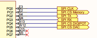
Schematic of the connections using SPI.
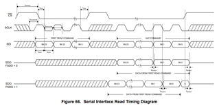
DAC Write bitfield specifications from DAC datasheet.
My theory is there is something wrong with the bitrate setting in SSIConfigSetExpClk() call but I can't figure out what is wrong. Any help would be greatly appreciated.