This thread has been locked.

If you have a related question, please click the "Ask a related question" button in the top right corner. The newly created question will be automatically linked to this question.

TMS570LC4357: Problems with DCAN shutdown by PCR

Part Number: TMS570LC4357

We are failing to shut down the DCAN peripheral as described in TRM:

27.11.1 Entering Global Power Down Mode.

The DCAN waits until a bus idle state is recognized. Then it will automatically set the Initbit to indicate that the global power down mode has been entered.

At the time of shutting down the bus is not idle - some other devices are driving the CAN bus. Our DCAN just finished some self test and it has been reset to init state.

But  we really need to disable this device independently to fact, that CAN bus isn't in idle state. 

The problem persists even when entered and confirmed a Local Power Down Mode:

27.12.1 Entering Local Power Down Mode,

With setting the PDA bits, the DCAN module indicates that the local power down mode has been entered.

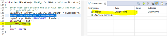
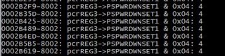
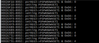
The DCAN is still regularly failing to enter the Global Power Down Mode as long as the CAN bus is not idle (i.e. setting of the corresponding PSPWRDWNSET bit fails).

We happened to come across a workaround that solves our problem but it is some undocumented behavior.

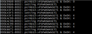
If we set just the SWR bit in DCAN CTL register, without setting the init bit, then we can reliably enter the Global Power Down Mode even when the CAN bus is not idle.

This behavior could possibly be explained as a forced reset state the DCAN is being held in (as the init bit has not provided a way out).

However, we would like to know how to properly enter the Global Power Down Mode when there is traffic on the bus, or if our workaround is legit.

  • Is the init bit of DCAN CTL set after the CAN bus gets idle?

    If the CAN module, for example DCAN1, is powered down, the clock will be gated to DCAN1 module and the DCAN1 module will not be clocked. However, if the CPU makes an access to them, they will be temporarily clocked for the singular access but then gated again after the access.

    After Init is set, writing 0x1 to SWR bit will reset the CAN module which means all the CAN registers are reset to their default value, but the DCAN module is still clocked.

    I mean that the PowerDown is different from SWR. 

  • The init bit is set when our problem arises, however the CAN bus does not get idle during the time.

    • The CAN bus is connected to a testing node that is trying to send an init message and because there is no other node to acknowledge the message yet, it is continually re-transmitting the message, hence the CAN bus does not get idle for 11 consecutive bits.

    What we are doing is performing a DCAN ECC self test at the system startup (CAN15 feature of the SPNU540A safety manual).

    At the end of that we successfully perform a DCAN SW reset like so:

      CTL = INIT
      CTL = CTL | SWR
      if CTL != 0x00001401 then   // Expected value after SW reset
        ERROR
      endif

    After this we want to turn off the DCAN, but setting is failing to set the power down bit in PCR->PSPWRDWNSET1 (for DCAN1 a DCAN2) or PCR->PSPWRDWNSET0 (for DCAN3 and DCAN4).

    It does not fail when the bus is idle and it fails for around one DCAN per startup when the bus is not idle.

    A workaround we don't understand but it seems to work is to set just the SWR bit like so:

     CTL = SWR // suspicious workaround before power down in PCR

    As a result of this, the CTL has a value of 0x00 and it is possible to reliably enter the Global Power Down Mode through PCR even when the bus is not idle.

    What is the correct way to turn off the DCAN when we the bus is not idle?

  • Writing to PCR->PSPWRDWNSET registers is the only way to power down or disable the clock to the device's peripherals. 

    The CAN bus becomes idle between two transmissions, after transmitting bits of EOF filed (7 bits).

    A workaround we don't understand but it seems to work is to set just the SWR bit

    How do you determine the CAN module is powered down after setting SWR bit?

  • We primarily want to solve the setting of the PCR->PSPWRDWNSET bit, since it is highly recommended by the TI Safety Manual (SPNU540A) - 5.13.7 Software Read Back of Written Configuration, so we are looking to perform it successfully.

    What are the conditions we need to meet for setting of the PCR->PSPWRDWNSET bit to not be dependant on the bus state?


  • The PCR->PSPWRDWNSET bit can be written to only in privileged mode. If in user mode, you need to clear the corresponding bit in PCR->PPROTSET register.

    If the modules are not used in your application, you can leave them inactive during startup. You can modify the code of periphInit(void):

    pcrREG3->PSPWRDWNCLR0 = 0xFFFFFFFFU;
    pcrREG3->PSPWRDWNCLR1 = 0xFFFFFFF00U;
    pcrREG3->PSPWRDWNCLR2 = 0xFFFFFFFFU;
    pcrREG3->PSPWRDWNCLR3 = 0xFFFFFFFFU;
     

    The default is inactive.

  • We are in privileged mode when working with the PCR and we are using the DCAN modules to perform ECC self tests as recommended by the safety manual (SPNU540A:CAN15) before deciding about further usage of the DCAN in our application.

    What we do is working great when there is no trafic on the bus. What we still did not find answer to is what is preventing us from seting the PCR->PSPWRDWNSET bit with trafic on the bus.

  • As stated in TRM:

    27.11.1 Entering Global Power Down Mode
    The global power down mode for the DCAN is requested by setting the appropriate Peripheral Power Down Set bit (PSPWRDWNSETx) in the PCR module.
    The DCAN then finishes all transmit requests of the message objects. When all requests are done, the DCAN waits until a bus idle state is recognized. Then it will automatically set the Init bit to indicate that the global power down mode has been entered.

    The module will be powered down automatically when the bus becomes idle. The CAN bus becomes idle between two CAN frames.

  • Don't be mistaken, I could almost recite this chapter. Our problem, if I were to go by this chapter, lays in:

    setting the appropriate Peripheral Power Down Set bit (PSPWRDWNSETx) in the PCR module.

    since it is highly recommended by the TI Safety Manual (SPNU540A) - 5.13.7 Software Read Back of Written Configuration. We are failing to check if the bit was set.

    Even after waiting for over 100 ms - long after many frames have passed, the bit does not become set without setting it repeatedly.

  • I knew you cited this chapter. I just did a test on LC43x HDK, and the PSP power down bit for DCAN2 is set. Here is my test code.

    1. DCAN1 and DCAN2 are connected: 2 nodes CAN network

    2. DCAN1 transmits data using mailbox 1, and the message ID is 0x1

    3. DCAN2 receives data using mailbox1, and message ID is 18 (different from ID of the msg from DCAN1)

    4. RTI compare0 gets interrupt every 500ms. In RTI ISR, set power-down bit for DCAN2 module:  pcrREG3->PSPWRDWNSET1 |= 0x00000004U;

        and read back the value of this register 

    5. Run the code and make sure the waveform is correct on oscilloscope, and DCAN1 keeps re-transmit this message (ID=1)

    6. Add breakpoint at asm("  nop"); the code execution will be suspended at this point, check the readback value

    /** @file HL_sys_main.c 
    *   @brief Application main file
    *   @date 11-Dec-2018
    *   @version 04.07.01
    *
    *   This file contains an empty main function,
    *   which can be used for the application.
    */
    
    /* 
    * Copyright (C) 2009-2018 Texas Instruments Incorporated - www.ti.com  
    * 
    * 
    *  Redistribution and use in source and binary forms, with or without 
    *  modification, are permitted provided that the following conditions 
    *  are met:
    *
    *    Redistributions of source code must retain the above copyright 
    *    notice, this list of conditions and the following disclaimer.
    *
    *    Redistributions in binary form must reproduce the above copyright
    *    notice, this list of conditions and the following disclaimer in the 
    *    documentation and/or other materials provided with the   
    *    distribution.
    *
    *    Neither the name of Texas Instruments Incorporated nor the names of
    *    its contributors may be used to endorse or promote products derived
    *    from this software without specific prior written permission.
    *
    *  THIS SOFTWARE IS PROVIDED BY THE COPYRIGHT HOLDERS AND CONTRIBUTORS 
    *  "AS IS" AND ANY EXPRESS OR IMPLIED WARRANTIES, INCLUDING, BUT NOT 
    *  LIMITED TO, THE IMPLIED WARRANTIES OF MERCHANTABILITY AND FITNESS FOR
    *  A PARTICULAR PURPOSE ARE DISCLAIMED. IN NO EVENT SHALL THE COPYRIGHT 
    *  OWNER OR CONTRIBUTORS BE LIABLE FOR ANY DIRECT, INDIRECT, INCIDENTAL, 
    *  SPECIAL, EXEMPLARY, OR CONSEQUENTIAL DAMAGES (INCLUDING, BUT NOT 
    *  LIMITED TO, PROCUREMENT OF SUBSTITUTE GOODS OR SERVICES; LOSS OF USE,
    *  DATA, OR PROFITS; OR BUSINESS INTERRUPTION) HOWEVER CAUSED AND ON ANY
    *  THEORY OF LIABILITY, WHETHER IN CONTRACT, STRICT LIABILITY, OR TORT 
    *  (INCLUDING NEGLIGENCE OR OTHERWISE) ARISING IN ANY WAY OUT OF THE USE 
    *  OF THIS SOFTWARE, EVEN IF ADVISED OF THE POSSIBILITY OF SUCH DAMAGE.
    *
    */
    
    
    /* USER CODE BEGIN (0) */
    /* USER CODE END */
    
    /* Include Files */
    
    #include "HL_sys_common.h"
    
    /* USER CODE BEGIN (1) */
    #include "HL_can.h"
    #include "HL_esm.h"
    #include "HL_sys_core.h"
    #include "HL_reg_pcr.h"
    #include "HL_rti.h"
    #include "HL_gio.h"
    #include "HL_het.h"
    
    #define D_COUNT  8
    
    uint32 cnt=0, error =0, tx_done =0;
    uint8 tx_data[D_COUNT][8] = {0};
    uint8 rx_data[D_COUNT][8] = {0};
    uint8 *tx_ptr = &tx_data[0][0];
    uint8 *rx_ptr = &rx_data[0][0];
    uint8 *dptr=0;
    
    void dumpSomeData();
    /* USER CODE END */
    
    /** @fn void main(void)
    *   @brief Application main function
    *   @note This function is empty by default.
    *
    *   This function is called after startup.
    *   The user can use this function to implement the application.
    */
    
    /* USER CODE BEGIN (2) */
    unsigned int pspVal=0;
    /* USER CODE END */
    
    int main(void)
    {
    /* USER CODE BEGIN (3) */
    
        /* enable irq interrupt in Cortex R4 */
        _enable_interrupt_();
    
        /** - writing a random data in RAM - to transmit */
        dumpSomeData();
    
        /** - configuring CAN1 MB1,Msg ID-1 to transmit and CAN2 MB1 to receive */
        canInit();
        rtiInit();
        hetInit();
    
        /* Enable RTI Compare 0 interrupt notification */
        rtiEnableNotification(rtiREG1,rtiNOTIFICATION_COMPARE0);
    
        /** - enabling error interrupts */
        canEnableErrorNotification(canREG1);
        canEnableErrorNotification(canREG2);
    
        /* Start RTI Counter Block 0 */
        rtiStartCounter(rtiREG1,rtiCOUNTER_BLOCK0);
    
    
        /** - starting transmission */
    //    pcrREG3->PSPWRDWNSET1 |= 0x00000004U;
    //    pcrREG3->PSPWRDWNCLR1 |= 0x00000004U;
    
        while(1)
        {
              canTransmit(canREG1, canMESSAGE_BOX1, tx_ptr); /* transmitting 8 different chunks 1 by 1 */
              while(tx_done == 0){};             /* ... wait until transmit request is through        */
              tx_done=0;
        }
    /* USER CODE END */
        return 0;
    }
    
    /* USER CODE BEGIN (4) */
    /* can interrupt notification */
    /* Note-You need to remove canMessageNotification from notification.c to avoid redefinition */
    void canMessageNotification(canBASE_t *node, uint32 messageBox)
    {
         /* node 1 - transfer request */
         if(node==canREG1)
         {
           tx_done=1; /* confirm transfer request */
         }
         /* node 2 - receive complete */
         if(node==canREG2)
         {
            while(!canIsRxMessageArrived(canREG2, canMESSAGE_BOX1));
            canGetData(canREG2, canMESSAGE_BOX1, rx_ptr); /* copy to RAM */
         }
    }
    
    void rtiNotification(rtiBASE_t *rtiREG, uint32 notification)
    {
    /*  enter user code between the USER CODE BEGIN and USER CODE END. */
        /* Toggle HET pin 0 */
        gioSetPort(hetPORT1, gioGetPort(hetPORT1) ^ 0x000000FF);
        pcrREG3->PSPWRDWNSET1 |= 0x00000004U;
        pspVal = pcrREG3->PSPWRDWNSET1 & 0x04 ;
        if(pspVal == 0x4 ){
            asm(" nop");
        }
        asm("  nop");
    }
    
    /* writing some data to ram  */
    void dumpSomeData()
    {
         uint32 tmp = 0x11;
    
         cnt = (D_COUNT*8)-1;
         dptr = &tx_data[0][0];
         *dptr = tmp;
    
         while(cnt--)
         {
            tmp = *dptr++;
            *dptr = tmp + 0x11;
         }
    }
    
    
    /* USER CODE END */
    
     https://e2e.ti.com/cfs-file/__key/communityserver-discussions-components-files/908/8780.TMS570LC43x_5F00_rtIBlinky.hcghttps://e2e.ti.com/cfs-file/__key/communityserver-discussions-components-files/908/3058.TMS570LC43x_5F00_rtIBlinky.dil

  • Thank you for taking the trouble and setting up a test. Modifying my test closer to yours resulted in a more specific outcome.

    It appears that traffic on the bus is clearing the pcrREG3->PSPWRDWNSET1 bit, and problem with the readback value is a result of that happening during its setting.

    My test steps now look like this:

    1. DCAN1 and DCAN2 are physically connected
    2. Verify DCAN2 is powered down (pcrREG3->PSPWRDWNSET1 & 0x04 is set).
      Log when executed repeatedly:
    3. Start transmission from DCAN1 -> CAN bus under 100% load, enforced by ACK off, confirmed by CAN probe:

    4. pcrREG3->PSPWRDWNSET1 & 0x04 is not set even though DCAN2 was not powered up. Readback when setting it fails around 1 in 4 times.
      Log when executed repeatedly:

    5. After disconnecting the cable connecting DCAN1 and DCAN2 and repeat step 4, the bit stays set.
      Log when executed repeatedly:

    C

    switch(test->step)
    {
      case 2u:
      {
        print("pcrREG3->PSPWRDWNSET1 & 0x04: %d", pcrREG3->PSPWRDWNSET1 & 0x04);
        break;
      }
      case 3u:
        saej1939_apiInitIfaceName(J1939_IFACE_DCAN1, J1939_BITRATE_250, CAN1_NODE, can1IfaceName);
        break;
      case 4u:
      {
        print("pcrREG3->PSPWRDWNSET1 & 0x04: %d", pcrREG3->PSPWRDWNSET1 & 0x04);
        print("setting PSPWRDWNSET1");
        pcrREG3->PSPWRDWNSET1 = 0x00000004U; // writing zeros has no effect
    print("pcrREG3->PSPWRDWNSET1 & 0x04: %d", pcrREG3->PSPWRDWNSET1 & 0x04); break; } }

    Could you please try reading the "pcrREG3->PSPWRDWNSET1 & 0x04" before setting it in your test too?

    Can you verify the BUS is under 100% load when setting the PSPWRDWNSET1 ? Perhaps deleting lines 118-119 in your example.

  • Any news? It is not solved yet.

  • If the CAN bus is active (a node is transmitting or has just finished transmission), the power-down request won't be taken and init bit of CAN control register won't be set.