Other Parts Discussed in Thread: HALCOGEN
Hi,
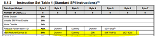
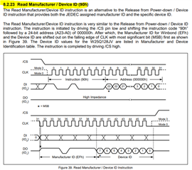
Customer want to connect W25Q128JV external EEPROM to TMS570LS1224, please see details below.
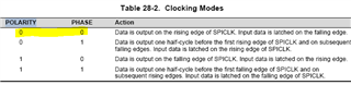
"Hello, I want to connect W25Q128JV external EEPROM to TMS570LS1224. i am using MibSPI3 for SPI communication. In Halcogen in MibSPi3 tab i have enabled master mode, set baudrate, charlength is set to 8 . In data Transfer tab i have selected CS0 and word length is set to 3. I am able to generate 24 bit word but after connecting to EEPROm i am not getting expected values. Below is the code i am using
/** @file sys_main.c
* @brief Application main file
* @date 11-Dec-2018
* @version 04.07.01
*
* This file contains the program to successfully run 24 bit SPI Data for ADC or DAC,
*
*/

/*
* Copyright (C) 2009-2018 Texas Instruments Incorporated - www.ti.com
*
*
* Redistribution and use in source and binary forms, with or without
* modification, are permitted provided that the following conditions
* are met:
*
* Redistributions of source code must retain the above copyright
* notice, this list of conditions and the following disclaimer.
*
* Redistributions in binary form must reproduce the above copyright
* notice, this list of conditions and the following disclaimer in the
* documentation and/or other materials provided with the
* distribution.
*
* Neither the name of Texas Instruments Incorporated nor the names of
* its contributors may be used to endorse or promote products derived
* from this software without specific prior written permission.
*
* THIS SOFTWARE IS PROVIDED BY THE COPYRIGHT HOLDERS AND CONTRIBUTORS
* "AS IS" AND ANY EXPRESS OR IMPLIED WARRANTIES, INCLUDING, BUT NOT
* LIMITED TO, THE IMPLIED WARRANTIES OF MERCHANTABILITY AND FITNESS FOR
* A PARTICULAR PURPOSE ARE DISCLAIMED. IN NO EVENT SHALL THE COPYRIGHT
* OWNER OR CONTRIBUTORS BE LIABLE FOR ANY DIRECT, INDIRECT, INCIDENTAL,
* SPECIAL, EXEMPLARY, OR CONSEQUENTIAL DAMAGES (INCLUDING, BUT NOT
* LIMITED TO, PROCUREMENT OF SUBSTITUTE GOODS OR SERVICES; LOSS OF USE,
* DATA, OR PROFITS; OR BUSINESS INTERRUPTION) HOWEVER CAUSED AND ON ANY
* THEORY OF LIABILITY, WHETHER IN CONTRACT, STRICT LIABILITY, OR TORT
* (INCLUDING NEGLIGENCE OR OTHERWISE) ARISING IN ANY WAY OUT OF THE USE
* OF THIS SOFTWARE, EVEN IF ADVISED OF THE POSSIBILITY OF SUCH DAMAGE.
*
*/


/* USER CODE BEGIN (0) */
#include "system.h"
#include "mibspi.h"
/* USER CODE END */

/* Include Files */

#include "sys_common.h"

/* USER CODE BEGIN (1) */
/* USER CODE END */

/** @fn void main(void)
* @brief Application main function
* @note This function is empty by default.
*
* This function is called after startup.
* The user can use this function to implement the application.
*/

/* USER CODE BEGIN (2) */
uint32 data1=0x05;
//uint32 data2=0x06;

uint32 txdata[6]={0};
uint32 rxdata[10];

/* USER CODE END */

int main(void)
{
/* USER CODE BEGIN (3) */

txdata[2]=data1 & 0x00FF;

txdata[1]=data1>>8 & 0x00FF;
txdata[0]=data1>>16 & 0x00FF;

txdata[2]=txdata[2]<<8;

mibspiInit();


mibspiSetData(mibspiREG3,0,txdata[2]);

mibspiTransfer(mibspiREG3,0);

while((mibspiIsTransferComplete(mibspiREG3,0)==FALSE));

mibspiGetData(mibspiREG3,0,rxdata);
/* USER CODE END */


while(1);
}


/* USER CODE BEGIN (4) */

/* USER CODE END */
"
Thank you in advance.
Regards,
Maynard