This thread has been locked.

If you have a related question, please click the "Ask a related question" button in the top right corner. The newly created question will be automatically linked to this question.

ADC issue on SITARA AM263x

Other Parts Discussed in Thread: SYSCONFIG

Hi,

I'm developing on a SITARA AM263x Evaluation Kit, using CCS 11 IDE and the provided mcu_plus_sdk_am263x_08_01_00_39 SDK.

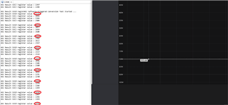
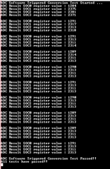
I noticed a strange behavior on internal ADC when I try to acquire more than three analog inputs triggered simultaneoulsy. In details, I modified the provided adc_soc_am263x-cc_r5fss0-0-nortos_ti-arm-clang example to force the trigger of multiple SOCs as showed in the code below and I applied a 1V DC Voltage just to the analog input configured to belong to the SOC 0 (ADCIN0). I left all the other analog inputs unconnected. Running the code I noticed that If I start a number of SOCs less or equal to 3 (SOC_NUM  macro), then the acquired SOC 0 channel seems to be correct (see SOC 0 raw value showed on Capture2.PNG file). When I increase the number of conversions (4 or more) the results are correct only on the first cycle of acquisitions; all the consecutive samples values seem wrong (see the same SOC 0 value on Capture1.PNG).

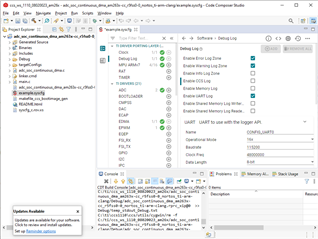
The ADC configuration is generated by the SysConfig Tool.

Is anything wrong on the code below?

Here the modified code:


* This example uses the ADC module to perform an ADC SOC conversion
* triggered by software.
*
* In this example ADC0 is used to convert the SOC, the user can also
* select a different one.
*
* This example also showcases how to configure and use the ADC module.
*/
#define LOOP_CNT 10
#define SOC_NUM 3
void adc_soc_software_main(void *args)
{
int i;
uint32_t baseAddr = CONFIG_ADC0_BASE_ADDR;
uint32_t loopCnt = 0;
uint16_t result[LOOP_CNT*SOC_NUM];
uint16_t socMask = 0;

/* Open drivers to open the UART driver for console */
Drivers_open();
Board_driversOpen();

for(i=0; i<SOC_NUM; i++)
{
socMask |= 1L<<i;
}

DebugP_log("ADC Software Triggered Conversion Test Started ...\r\n");

while(loopCnt<LOOP_CNT)
{
/* Clear any pending interrupts */
ADC_clearInterruptStatus(baseAddr, ADC_INT_NUMBER1);

//ADC_forceSOC(baseAddr, ADC_SOC_NUMBER0);
ADC_forceMultipleSOC(baseAddr, socMask);
while(ADC_getInterruptStatus(baseAddr, ADC_INT_NUMBER1) == false)
{
/* Wait for the SOC conversion to complete */
}

for(i=0; i<SOC_NUM; i++)
{
result[SOC_NUM*loopCnt+i] = ADC_readResult(CSL_CONTROLSS_ADC0_RESULT_U_BASE, i);
}

loopCnt++;
}

loopCnt = 0;
while(loopCnt<LOOP_CNT)
{
for(i=0; i<SOC_NUM; i++)
{
DebugP_log("ADC Result SOC%d register value : %d\r\n", i, result[SOC_NUM*loopCnt+i]);
}

DebugP_log("\r\n");
loopCnt++;
}

/* Clear and disable interrupt */
ADC_disableInterrupt(baseAddr, ADC_INT_NUMBER1);
ADC_clearInterruptStatus(baseAddr, ADC_INT_NUMBER1);
/* Power down the ADC */
ADC_disableConverter(baseAddr);

DebugP_log("ADC Software Triggered Conversion Test Passed!!\r\n");
DebugP_log("All tests have passed!!\r\n");

Board_driversClose();
Drivers_close();
}


Capture1.PNG

Capture1.PNG

Capture2.PNG

  • Hi Vanni,

    Can you try the same example with same modifications, but disable the "Enable CCS Log" in Debug Log and try again? The CCS log is very intrusive (disable interrupt and others).

    Best regards,

    Ming

  • Hi Ming,

    thanks for supporting me.

    I've just applied your suggestion but this did not resolve the problem. The strange think is that all is working only for maximum three simultaneous triggered SOCs.

    I add the zipped project for further investigations.

    adc_soc_software_am263x-cc_r5fss0-0_nortos_ti-arm-clang.zip

  • Hi Vanni,

    Can you decrease the "ADC Clock Prescaler" from /4 to /2 or even /1?

    Best regards,

    Ming

  • Hi Ming,

    I tried with both the suggested prescaler values, still not working. I just noticed a slight improvement with the prescaling factor /1, but the read samples are still wrong when triggering four or more acquisitions. I tried also with different sampling window values (both lower and higher) with the same result.

    Best regards,

    Vanni Vinti

  • Hello Vanni,

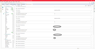
    Please make sure to configure the ADC channel and sample window for each SOC.

    When using SOC_NUM > 4, please configure the channels and sample window of SOC4, SOC5,...

    Can you please attach the Capture1.PNG and Capture2.PNG again? I am unable to access it from the post.

    Thanks

    Sanjeev

  • Hi Sanjeev,

    I also tried to configure all the sample windows of all the sixteen SOCs to 15.

    On the figures below you can see the results:

    - when the multiple acquired SOC are three or less, I can see a correct value on SOC0 (the only one with a 1V DC voltage applied). Please check the raw value equal to 1215 (mostly) on Capture_ko.PNG.

    - when the multiple acquired SOCs are four (or even more), excluding the first cycle sampled value on SOC0, all the remaining samples are wrong (referring to the same SOC0, of course), Please see Capture_ok.PNG.

    BR,

    Vanni

  • Hello Vanni,

    We are working to reproduce the issue at our end. We used the the CCS project (the zip you shared) along with the mentioned SDK version mcu_plus_sdk_am263x_08_01_00_39. The issue is not reproducible at our end yet - we see valid ADC results for all 4 SOCx when fed with a constant voltage to all channels.

    Details of our setup:

    We are using AM263x ControlCard with PG1.0A HS-FS sample. We have the bootmode set to noboot (1011), use CCS11.1 to load the generated .out. ADC reference: System VREF source select switch SW8 on ControlCard is set to position 1-2

    To help reproduce the issue, can you provide any other relevant details of your setup?

    Based on code review, we see that the code waits for INT1. And INT1 has EOC0 as source, but not the end of conversion of last SOC (EOC3). Is this intentional? Can you change INT1 source to EOC3 and try?

    Thanks

    Sanjeev

  • Hello Vanni,

    We reproduced the issue

    We'll investigate further and get back to you

    Thanks

    Sanjeev

  • Hi Sanjeev,

    happy to see you were able to reply the same behavior on your board.

    To answer to your question about the INT1 management, I left it linked to the SOC0 just because I was interested only to the end of conversion of this SOC which had an applied  DC  voltage in input.

    Anyway I can confirm you I also tried to enable the INT1 on the latest SOC in the chain, but the result was the same.

    BR,

    Vanni

  • Hello Vanni,

    The issue at our end is due to a poorly driven source (a potentiometer used to generate the 1v input from a 3.3v source on the ControlCard). We see expected results when using a low impedance source to feed the ADC inputs.

    What source are you using to generate the 1v input?

    Thanks

    Sanjeev

  • Hello Sanjeev,

    I was using a portable oscilloscope with built-in signal generation feature. After your indication I tried with power supply and I can confirm that I'm now seeing correct values after every acquisition loop. I'm just wondering why  the wrong values were higher than expected by the way.

    Thanks,

    Vanni