This thread has been locked.

If you have a related question, please click the "Ask a related question" button in the top right corner. The newly created question will be automatically linked to this question.

AM2434: VMON_VSYS pin function confirmation

Part Number: AM2434

Hi Champ,

I am asking for my customer. Sorry for that I don't know much about Arm-based MCU.

Customer's current design follows our EVM board with the pin VMON_VSYS in below screenshot.

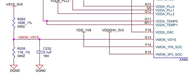
I would like to ask the function and specification of this pin (VMON_VSYS) can be explained more clearly and easily. Though we have read the specification, still don't quite understand the purpose of this function. Would you elaborate more in details please ?

Also, the voltage level measured on VMON_VSYS is about 490mV from customer's design. Is it well-designed to meet the spec. ?

Thanks for any reply.

Best regard.

  • Hi Johnny,

    The AM243x Datasheet has a lot of good information on the VMON_VSYS rail, particularly in section 6.3.23.4, the VMON Signal Descriptions section.  It says:

    Voltage monitor input, fixed 0.45 V (+/-3%) threshold. Use with external precision voltage divider to monitor a higher voltage rail such as the PMIC input supply.

    VMON_VSYS is intended to be used to monitor the primary system power rail (i.e. the supply power to the system that is the input to the PMIC or discrete power rail generation solution).  In your customer's schematic, it looks like VMON_VSYS is intended to monitor a system wide 5.0V rail, which would be a good usecase, assuming that rail is used to generated the other rails used by the AM2434.  However, the customers 0.495V is too high for the specified voltage requirement of 0.45V (+/-3%), which is 0.4365V to 0.4635V.  R262 and R255 should be adjusted to make the voltage within the range specified.

    Thanks,
    Mike

  • Hi Mike,

    Thank you for the reply. There are few questions that I still get confused and like to follow up.

    1. If the design voltage exceeds the assumed protection by 0.45+/-3%, what will happen ? Will the system be latched ? Or is there any other mechanism ?

    2. Since I already knew that the voltage on VMON_VSYS must be precisely controlled at 0.45+/-3%, but exactly I still don't know the function of this pin VMON_VSYS, why must it be designed at this voltage if it is only monitoring the 5V function ? The reason that I am asking this  because in the real application 5.0V rail itself may be actually floating a little bit, and considering the inaccuracy on the resistance...etc., it is actually difficult to accurately control within the threshold (0.45+/-3%). Furthermore, it is found out that if the VMON_VSYS on the TI-AM243 development board is divided by 5V, it is actually about 0.49V, not within the threshold.

    Would you kindly help on these ? Many thanks.

    Regards.

  • Hi Johnny,

    I apologize, I misread the datasheet on the 0.45V +/-3%.  This is a single threshold voltage, not a range that it needs to stay within.  As long as the voltage on the pin is greater than 0.45V +/-3%, the monitor is happy.  It only generates the flag when the voltage dips below 0.45V +/-3%.  The voltage divider should be set up so that when the system voltage being monitored drops to a user defined level, the output of the voltage divider is 0.45V.  As long as the system voltage stays above this level, no flag is set.  But when it drops below the defined level, the undervoltage detection logic sets the flag.

    So for the AM243 GPEVM (and the customers schematic) that use 100k and 11k resistors on a 5V line, this sets the user defined voltage level at 4.54V.  As long as the VSYS_5V0 rail is actually above 4.54V, the output of the voltage divider is greater than 0.45V, and no flag is set.  But when the VSYS_5V0 rail drops below 4.54V (say to 4.25V), the output of the voltage divider drops below 0.45V (0.42V at 4.25V rail), and the flag is set to alert the system than an UV event has occurred.